3 runners, 4 attachment clutch/brake adjustment, Attachment – Ariens 939 SNO-THRO 939001 User Manual
Page 18
5 - 18
5.3 RUNNERS
Runners should be adjusted as conditions require
(Figure 14).
1. Position unit on a hard, flat, smooth level surface.
2. Adjust runners by inserting a spacer of desired
thickness under center of scraper blade, loosen
runner hardware, slide runners to flat surface.
Allow 1/8 in. (3 mm) between scraper blade and
hard smooth surfaces. Allow 1-1/4 in. (30 mm)
between scraper blade and uneven or gravel
surfaces. Retighten hardware.
NOTE: Keep housing level by adjusting runners
equally.
5.4 ATTACHMENT CLUTCH/BRAKE
ADJUSTMENT
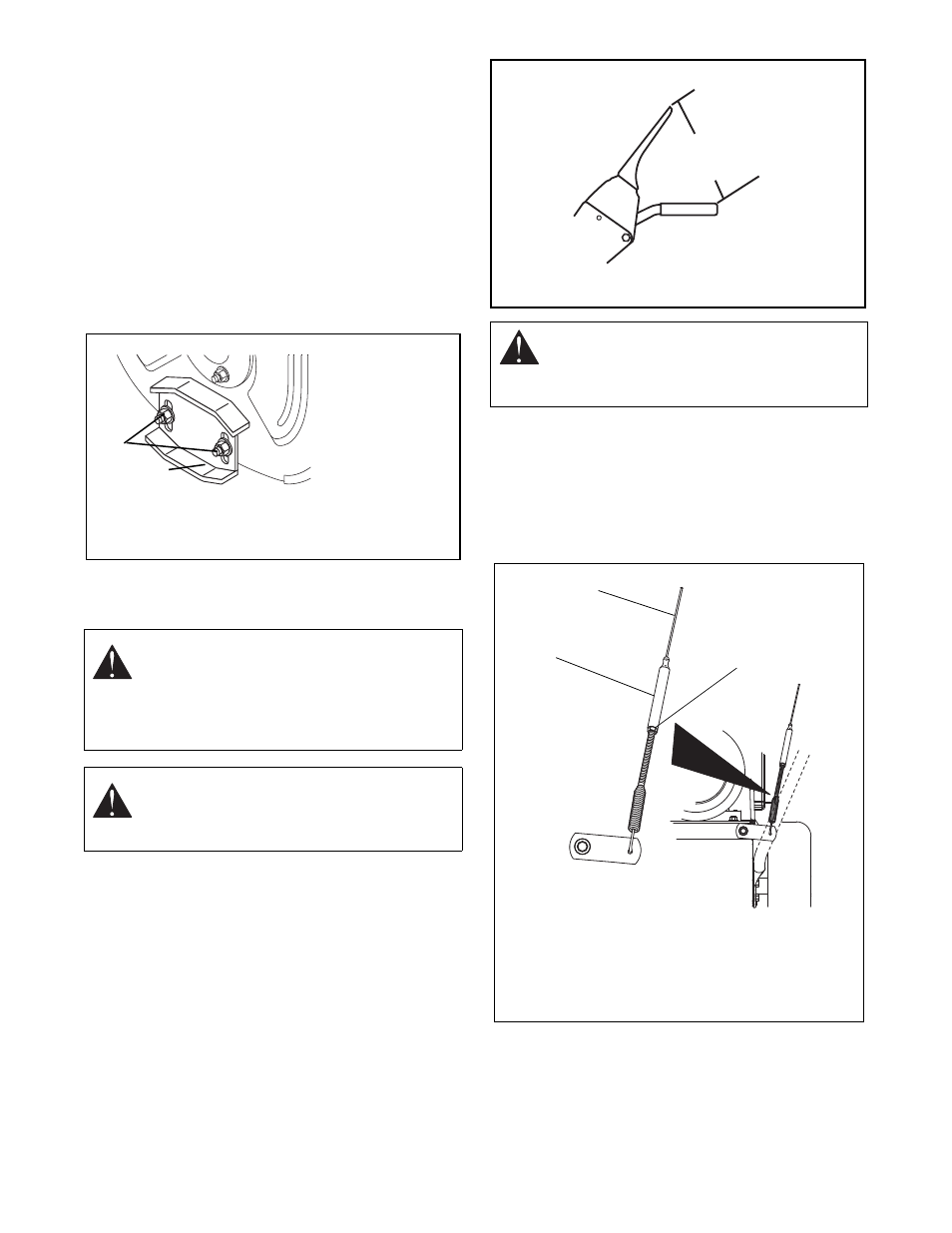
1. Check attachment clutch lever measurement:
a. Start engine and run at full throttle.
b. Slowly squeeze the attachment clutch lever
until auger shaft begins to rotate.
c. Measure the distance from the end of clutch
lever to the handlebar as shown in Figure 15.
The distance between the end of the clutch
lever and the handlebar should be 5-5/8 - 6-1/4
in. (14.3 - 15.9 cm).
d. Shut off engine.
e. If clutch lever measurement is within specified
range, no adjustment is necessary. If clutch
lever measurement is outside the specified
range, follow steps 2 - 7.
2. Loosen jam nut on attachment clutch cable
adjustment barrel (Figure 16).
Turn adjustment barrel up the cable to decrease
the distance between clutch lever and handlebar.
Turn the adjustment barrel down the cable to
increase the distance between clutch lever and
handlebar.
3. Check attachment clutch lever measurement and
tighten the jam nut on the attachment clutch cable
adjustment barrel when the clutch lever
measurement is in range. Proceed to step 6.
If clutch cannot be adjusted to specified range with
the cable adjustment alone, perform steps 4 – 5.
WARNING: IMPROPER ADJUSTMENT
could result in unexpected movement of
auger and impeller, causing death or serious
injury. AUGER / IMPELLER MUST STOP
within 3 seconds when Attachment Clutch/
Impeller Brake Lever is released.
WARNING: Adjustment procedure requires
running engine with the belt cover off. AVOID
INJURY. Read and understand the entire
Safety section before proceeding.
2
1
OS0482
1. Runner
2. Runner Hardware
Figure 14
CAUTION: The attachment clutch cable must
be slightly slack when the clutch lever is
disengaged. The attachment brake will not
function properly if the cable is too taut.
Attachment Clutch Lever
OS0458
(14,3 cm - 15,9 cm)
5-5/8 - 6-1/4 in.
Figure 15
Figure 16
3. Attachment Clutch
Cable
4. Jam Nut
5. Adjustment Barrel
2
1
3
OS7385