Alamo SX15 User Manual
Sx15, Operator’s manual
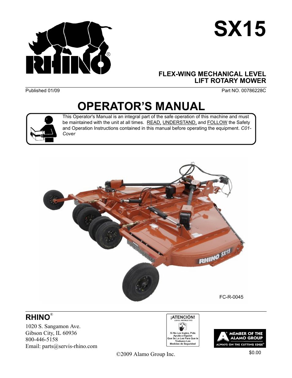
Table of contents
Document Outline
- SX15
- OPERATOR’S MANUAL
- To the Owner/Operator/Dealer
- Alamo Group Ag. Division is willing to provide
- one (1) AEM Mower Safety Practices Video
- TABLE OF CONTENTS
- General Safety Instructions and Practices
- Operator Safety Instructions and Practices
- Equipment Operation Safety Instructions and Practices
- Connecting or Disconnecting Implement Safety Instructions and Practices
- Maintenance and Service Safety Instructions and Practices
- Decal Location
- SAFETY SECTION
- 1. D389 1 DECAL SHEET Multi Hazard
- 2. D390 1 DECAL SHEET Pull Type Unit Hazards
- 3. D388 1 DECAL SHEET Driveline Hazards
- 4. D395 3 IMPORTANT Replace Blades in Pairs
- 5. 00753840 2 DANGER Wing Lowering Safety
- 6. 00756004 4 DANGER Shield Missing
- 7. 00756005 2 DANGER Rotating Driveline
- 8. 00771283 1 WARRANTY 5 - Year
- 9. D137 2 INSTRUCT CCW Blade Rotation
- 10. D138 1 INSTRUCT CW Blade Rotation
- 11. 03200347 1 REFLECT SMV
- 12. 1458392 2 REFLECT Red Reflector
- 13. 1458393 1 REFLECT Amber Reflector
- 14. D302 4 LOGO Rhino Logo (4x6)
- 15. D303 2 LOGO Rhino Logo (4x16)
- 16. 00786231 2 NAME SX 15 - Large
- 17. 99102 2 NAME Rhino Name Logo
- 18. 00786230 1 NAME SX 15 - Small
- 19. 00760657 1 IMPORTANT Genuine Rhino Parts
- 20. nfs 1 SERIAL PLATE Serial Number Plate
- 21. 00776031 1 INSTRUCT Canister, Operators Manual
- 22. 10058000 3 --------------- Bolt
- 23. 00024100 6 --------------- Flatwasher
- 24. 02959924 3 --------------- Locknut
- 25. 00786228C 1 --------------- Operator’s Manual (Inside Canister)
- 26. D482 1 WARNING Jack Positioning
- 27. 1006348 1 WARNING Explosion Hazard
- Decal Description
- Federal Laws and Regulations
- Attention Owner/Operator
- INTRODUCTION SECTION
- DEALER SET-UP INSTRUCTIONS
- 1. Position center section on flat surface. Elevate approximately 10 inches from ground to permit the installation of wings.
- 2. Installing Right Wing, Left Wing, or Counter Weight (#1). Align hinges, making sure to include spacer tube (#4). Insert Hinge Rod (#6) from front of machine. (To facilitate installing hinge rod, insert a long 3/4" bolt or rod through the first few...
- 3. Install Tongue (#1) pivot tubes into clevis type openings at front of Center Section. Insert Pivot Pin (#2) through outside clevis flat, pivot tube, and then inside clevis flat. Rotate head of pin so that the hole on the head of the pin lines up w...
- 4. Install Center Axle Legs (#1or #2) and Outer Axle (#16) to Center Axle (#2) using 3/4" x 4" bolts (#18), and lock nuts (#7). Tighten securely. NOTE: Install bolts through flats on Axle tube (#6) and through gauge wheel Axle Legs (#1or #5) and then...
- 5. Install Main Driveline. Attach Driveline Yoke to Mower Divider Gearbox. Tighten Clamping Cone Yoke to 75 lb-ft torque.
- 6. Attach Slip Clutch end of Wing Driveline to shaft on Divider Gearbox . Insert clamp bolts or clamping cone depending on driveline type and tighten securely (75 lb-ft torque).
- 7. Install Center Divider Gearbox Shield. Remove the top two bolts and lockwashers from the Center Gearbox. Install the shield on the Center Divider Gearbox and replace with longer hardware.
- 8. Install opposite end of Wing Driveline to outer Gearbox input shaft. Secure yoke on shaft by tightening taper pin to 75 ft/lbs. located on Driveline Clamp. NOTE: To facilitate removal of Clutches and Yokes from splined shafts in the future, it wou...
- 9. Install Center Section Hydraulic Lift Cylinder with base end attached to Spring Support. Note: See hydraulic schematic for more details.
- 10. Install Transports Bars on lower Cylinder Pin and retain using cotter pin. Install Transport Bar over pin welded to wing frame to store when not in use.
- 11. Check oil levels in all boxes. Add lube if required.
- FRONT AND REAR DEFLECTORS (Standard Equipment) CHAINGUARDS (OPTIONAL EQUIPMENT)
- FRONT AND REAR DEFLECTORS (Standard Equipment) CHAINGUARDS ( OPTIONAL EQUIPMENT)
- HYDRAULIC SYSTEM ASSEMBLY
- 1. This unit can be operated on any tractor which has at least two remote outlets.
- 2. If tractor has only two outlets, one must be used to control the center axle and the other to control both wings by placing a tee in the hoses between the cylinders. NOTE: When both wing hydraulic cylinders are operated by one valve spool, indepen...
- 3. If a three-spool valve bank is required, then assemble it on a mounting bracket and install on the tractor fender at desired location. (See valve bank plumbing diagram for further details).
- HYDRAULIC THREE-SPOOL VALVE ACCESSORY (EXTRA EQUIPMENT)
- WINCH AND STAND ACCESSORY
- HYDRAULIC SYSTEM ASSEMBLY
- RHINO SX15 ROTARY MOWER
- OPERATION INSTRUCTIONS
- 1. Standard Equipment and Specifications
- 3. TRACTOR REQUIREMENTS
- Tractor Requirements and Capabilities
- 3.1 ROPS and Seat Belt
- 3.2 Tractor Safety Devices
- 3.3 Front End Weight
- 3.4 Drawbar
- 3.5 Power Take Off (PTO)
- 3.6 Tire Spacing
- 4. GETTING ON AND OFF THE TRACTOR
- 5. STARTING THE TRACTOR
- 6. CONNECTING THE MOWER TO THE TRACTOR
- 6.1 Connecting the Mower Tongue to the Tractor
- 1. Ensure the tractor is equipped with the correct PTO shaft and the drawbar is set at the correct length.
- 2. Using the parking jack, position the tongue clevis to the height of the tractor drawbar. Adjust the mower tongue clevis to be level and parallel with the tractor drawbar using the control rod connecting the mower tongue clevis to the deck.
- 3. Board the tractor and start the engine. Back the tractor to the mower aligning the drawbar hitch hole with the mower tongue clevis. Turn off the tractor engine, place the tractor in park, and set the parking brake before dismounting.
- 4. To attach the mower, place two 1” flatwashers (1) positioned under top lip of tongue clevis and to the top of drawbar. Insert a 1” diameter grade 5 or 8 bolt (2) through clevis and drawbar and retain in position with a 1” locknut (3). Tighte...
- 5. Securely attach the mower safety chain to the tractor drawbar or drawbar support frame.
- 6. Lower the jack until the tongue is completely supported by the drawbar. Remove jack from the tongue and place on storage bracket of mower.
- 6.2 Connecting Mower Hydraulic Lines to the Tractor
- 6.1 Connecting the Mower Tongue to the Tractor
- 7. SETTING THE MOWER
- 7.1 Setting Deck Height
- 1. Place the tractor and mower on a level surface and lower both wings.
- 2. Use the center section hydraulic cylinder to set the mower at approximately 3/4” above the desired cutting height. The additional height is necessary so that after the mower has been leveled, the deck pitch can be set such that the front of the ...
- 3. Shut down the tractor, place the transmission in park, and set the parking brake before dismounting.
- 4. Level the mower deck front to rear by adjusting the leveling rods linking the tongue to the rear axle. DO NOT allow feet or other body part underneath the mower when making adjustments. To adjust rod length, loosen jamnut and screw turnbuckles. To...
- 5. Level the mower side to side by manipulating one lower lift arm length. On most tractors, at least one of the lift arms is designed to allow for manipulation of its length. Shortening or extending will allow for deck leveling from side to side.
- 7.2 Setting Deck Pitch
- 7.1 Setting Deck Height
- 8. DRIVELINE ATTACHMENT
- 9. PRE-OPERATION INSPECTION AND SERVICE
- 10. DRIVING THE TRACTOR AND IMPLEMENT
- 11. OPERATING THE TRACTOR AND IMPLEMENT
- 12. DISCONNECTING THE MOWER FROM THE TRACTOR
- 13. MOWER STORAGE
- 14. TRANSPORTING THE TRACTOR AND IMPLEMENT
- 15. TROUBLESHOOTING GUIDE
- Problem Possible Cause Remedy
- Check for loose nuts on Tighten if loose.
- bladeholder and blades.
- Check for bent output shaft. If Replace shaft if bent.
- shaft is bent, oil will normally
- leak from bottom seal.
- Check to see if blades are Free blades so they swing.
- swinging.
- Check for even wear on each Weigh blades. Weight should be within
- blade tip. Were both blades 1 oz. Always replace both blades.
- changed at the same time?
- Blade broken. Replace blades, in sets.
- Blade carrier bent. Replace carrier.
- Blade hub not properly seated Remove hub, check tapered spline
- on shaft. shaft, clean and replace.
- New blade or bolts matched with Replace blades or bolts in sets.
- worn blade or bolts.
- Drivelines not phased correctly. Replace driveline.
- Implement & tractor yokes must
- be in line.
- Blade rotation incorrect. Use correct blade for carrier rotation.
- Carrier RPM too low. Use correct PTO speed and check for
- correct gearbox ratio.
- Mower not level. Adjust machine.
- Tractor tires mashing down grass. Move tires out of cutter overlap area.
- Minimum 60” inside tires.
- Ground speed too fast. Reduce ground speed
- Blades locked back. Free blades.
- Blades riding up due to blade bolt Replace blade bolts.
- wear.
- Blade Wears too Fast Cutting in sandy or rocky conditions Increase cutting height.
- Soft “will fit” blades. Use genuine Rhino HT blades.
- Worn Bearing. Replace Bearing.
- Bent Shaft. Replace Oil Seal and Shaft.
- Oil Seal Race rough. Replace Shaft or repair Race.
- Oil Seal installed wrong. Replace Seal.
- Oil Seal not sealing in the housing. Replace Seal or use a sealant on O.D.
- of Seal.
- Oil level too high. Drain oil to proper level.
- Gasket damaged. Replace Gasket.
- Bolts loose. Tighten Bolts.
- open.
- in turns. drawbars.
- plates warped. of manuals.
- Too much power for Reduce ground speed and
- Slip Clutch. material intake.
- Oil on Facings. Replace Facings.
- Friction Facings glazed. Clean with emery cloth.
- Oil squirting from breather Oil leaking by piston ring. (A small Do not carry cutter on cylinder. (Use
- Piston ring worn. Replace piston ring.
- Cylinder wall scored or pitted. Replace cylinder.
- Wrong piston ring on piston. Use correct piston rings.
- Blades unable to cut that part of ground speed of tractor but keep
- grass pressed down by path of engine running at full PTO rpm. Move
- tractor tires. rear tires to 60” inside of tires so wing
- blades will pick up grass.
- Dull blades. Sharpen or replace blades.
- Height of cutter lower at rear or front. See cutting height instructions.
- Improper type lubricant. Replace with proper lubricant. See
- Maintenance Section.
- Excessive trash build-up around Remove trash.
- gear box.
- Bearing or gears set-up improperly. Consult your dealer.
- Operate
- Valve not connected properly. Re-plumb valve.
- Quick coupler not completely Complete connection.
- connected.
- MAINTENANCE SECTION
- Lubrication
- Problem Possible Cause Remedy
- DRIVELINES
- BLADE SERVICING
- BLADE SHARPENING
- BLADE REMOVAL
- BLADE CARRIER REMOVAL
- BLADE CARRIER INSPECTION
- BLADE CARRIER INSTALLATION
- SLIP CLUTCH
- SEASONAL CLUTCH MAINTENANCE
- 1. Loosen nuts (Figure Mnt-R-0353) on springs until the springs are free, yet remain secure on bolts.
- 2. Attach cutter to tractor and start the tractor. Set the engine speed at 1200 RPM.
- 3. Mark outer plates as shown in Figure Mnt-R-0353
- 4. Engage the PTO (approximately one second) and then quickly disengage it. The friction lining plates should break loose (check the mark).
- 5. Turn tractor off. Tighten the nuts on the coil spring clutch to their original position of 1-5/16” compressed spring length.
- HYDRAULIC HOSES
- SKID SHOES
- MOWER STORAGE
- 1. Thoroughly clean the cutter.
- 2. Lubricate the cutter as covered in Maintenance Section.
- 3. Tighten all bolts and pins to the recommended torque.
- 4. Check the cutter for worn or damaged parts. Make replacements immediately.
- 5. Store the cutter in a clean, dry place with the cutter housing resting on blocks.
- 6. Use spray touch-up enamel where necessary to prevent rust and maintain the appearance of the cutter.
- TORQUE CHART
- GEARBOX SERVICING
- 1. Caulking Gun w/ Locktite #5900
- 2. Impact Wrench
- 3. Ball Pin Hammer
- 4. Torque Wrench-Inch Pound
- 5. Retaining Ring Pliers
- 6. 3/16” Punch
- 7. 13 mm Socket
- 8. Locktite #270
- 1. 2 Shim
- 2. 4 Bolt
- 3. 1 Gas Solid Plug
- 4. 1 Cover
- 5. 1 Crow
- 6. 1 Bearing
- 7. 1 Casting & Machine
- 8. 2 Snap Ring
- 9. 1 Oil Seal
- 10. 1 Input Shaft
- 11. 1 Castle Nut
- 12. 1 Conic Pinon
- 13. 1 Shim
- 14. 1 Bearing
- 15. 1 Oil Seal
- 16. 1 Screen Protection
- 17. 1 Cotter Pin
- 18. 1 Output Shaft
- 19. 1 Flat Washer
- 20. 1 Castle Nut
- 21. 1 Plug
- 22. 1 Bearing
- 23. 1 Oil Seal
- 24. 1 Sham
- 25. 1 Gas Oil Headless Plug
- 26. 1 Bushing Grooved
- 27. 1 Cotter Pin
- 28. 1 Breather Plug
- GEARBOX SERVICING
- RIGHT ANGLE GEARBOX ASSEMBLY & DISASSEMBLY PROCEDURES
- 1. Place gearbox on appropriate work surface. Remove bolts retaining top cover plate.
- 2. Drive sharp object (screwdriver) through seal #9 and force out of housing. Repeat procedure for back cap #23.
- 3. Remove retaining rings #8 from both sides of gearbox. NOTE location of shims between bearing and retaining ring and mark for later reinstallation.
- 4. Remove shaft from housing by pressing on end of shaft. Bearing cone #6 and gear #5 will remain in housing. Remove by lifting out. Press cone off rear end of shaft.
- 1. Remove protective shield # 16 by prying out. Remove bottom seal # 15 using same procedure as in step 2 under input shaft.
- 2. Remove cotter pin # 17 and slotted nut # 11 from to end of output shaft.
- 3. Using long punch or bar inserted through top press shaft # 18 out bottom end.
- 4. Remove gear # 12 shim # 13 and bearing cone #14 from main housing. Note and mark shims # 13 so they may be reused during assembly.
- 5. Using lon punch or bar press bearing cup # 14 from main housing at ouput and top. Press bearing cone from lower end of shaft #18.
- 1. Press bearing cup # 6 into housing. Install gear adjusting shims # 1 on input side of gearbox if any were present at disassembly. Install retaining ring # 8
- 2. Drop gear # 5 and bearing cone # 6 into place in gear box. Insert shaft # 10 through gear # 5 and bearing #6 as far as possible. Press ball bearing # 22 as far as possible on back side of gear box. Install preload adjusting shims # 1 against beari...
- 3. Check gear backlash. Backlash should always be present and should be between .005 and .012 inches. If not then shims # 1 must be exchanged between input and rear sides of gearbox. To increase backlash place a thinner shim on input side and thicker...
- 4. Press in all seals and caps and install top cover plate.
- SX15
- FLEX-WING MECHANICAL LEVEL
- LIFT ROTARY MOWER
- RHINO
- LIMITED WARRANTY
- 1. LIMITED WARRANTIES
- 1.01. Servis-Rhino warrants for one year from the purchase date to the original non-commercial, governmental, or municipal purchaser (“Purchaser”) and warrants for six months to the original commercial or industrial purchaser (“Purchaser”) th...
- 1.02. Manufacturer will replace for the Purchaser any part or parts found, upon examination at one of its factories, to be defective under normal use and service due to defects in material or workmanship.
- 1.03. This limited warranty does not apply to any part of the goods which has been subjected to improper or abnormal use, negligence, alteration, modification, or accident, damaged due to lack of maintenance or use of wrong fuel, oil, or lubricants, ...
- 1.04. Except as provided herein, no employee, agent, Dealer, or other person is authorized to give any warranties of any nature on behalf of Manufacturer.
- 2. REMEDIES AND PROCEDURES.
- 2.01. This limited warranty is not effective unless the Purchaser returns the Registration and Warranty Form to Manufacturer within 30 days of purchase.
- 2.02. Purchaser claims must be made in writing to the Authorized Dealer (“Dealer”) from whom Purchaser purchased the goods or an approved Authorized Dealer (“Dealer”) within 30 days after Purchaser learns of the facts on which the claim is based
- 2.03. Purchaser is responsible for returning the goods in question to the Dealer.
- 2.04. If after examining the goods and/or parts in question, Manufacturer finds them to be defective under normal use and service due to defects in material or workmanship, Manufacturer will:
- (a) Repair or replace the defective goods or part(s) or
- (b) Reimburse Purchaser for the cost of the part(s) and reasonable labor charges (as determined by Manufacturer) if Purchaser paid for the repair and/or replacement prior to the final determination of applicability of the warranty by Manufacturer.
- 2.05. Purchaser is responsible for any labor charges exceeding a reasonable amount as determined by Manufacturer and for returning the goods to the Dealer, whether or not the claim is approved. Purchaser is responsible for the transportation cost for...
- 3. LIMITATION OF LIABILITY.
- 3.01. MANUFACTURER DISCLAIMS ANY EXPRESS (EXCEPT AS SET FORTH HEREIN) AND IMPLIED WARRANTIES WITH RESPECT TO THE GOODS INCLUDING, BUT NOT LIMITED TO, MERCHANTABILITY AND FITNESS FOR A PARTICULAR PURPOSE.
- 3.02. MANUFACTURER MAKES NO WARRANTY AS TO THE DESIGN, CAPABILITY, CAPACITY, OR SUITABILITY FOR USE OF THE GOODS.
- 3.03. EXCEPT AS PROVIDED HEREIN, MANUFACTURER SHALL HAVE NO LIABILITY OR RESPONSIBILITY TO PURCHASER OR ANY OTHER PERSON OR ENTITY WITH RESPECT TO ANY LIABILITY, LOSS, OR DAMAGE CAUSED OR ALLEGED TO BE CAUSED DIRECTLY OR INDIRECTLY BY THE GOODS INCLU...
- 3.04. NO ACTION ARISING OUT OF ANY CLAIMED BREACH OF THIS WARRANTY OR TRANSACTIONS UNDER THIS WARRANTY MAY BE BROUGHT MORE THAN TWO (2) YEARS AFTER THE CAUSE OF ACTION HAS OCCURRED.
- 4. MISCELLANEOUS.
- 4.01. Proper Venue for any lawsuits arising from or related to this limited warranty shall be only in Guadalupe County, Texas.
- 4.02. Manufacturer may waive compliance with any of the terms of this limited warranty, but no waiver of any terms shall be deemed to be a waiver of any other term.
- 4.03. If any provision of this limited warranty shall violate any applicable law and is held to be unenforceable, then the invalidity of such provision shall not invalidate any other provisions herein.
- 4.04. Applicable law may provide rights and benefits to purchaser in addition to those provided herein.
- LIMITED WARRANTY
- Back Cover Rotary.pdf
- SX15
- FLEX-WING MECHANICAL LEVEL
- LIFT ROTARY MOWER
- RHINO
- LIMITED WARRANTY
- 1. LIMITED WARRANTIES
- 1.01. Servis-Rhino warrants for one year from the purchase date to the original non-commercial, governmental, or municipal purchaser (“Purchaser”) and warrants for six months to the original commercial or industrial purchaser (“Purchaser”) th...
- 1.02. Manufacturer will replace for the Purchaser any part or parts found, upon examination at one of its factories, to be defective under normal use and service due to defects in material or workmanship.
- 1.03. This limited warranty does not apply to any part of the goods which has been subjected to improper or abnormal use, negligence, alteration, modification, or accident, damaged due to lack of maintenance or use of wrong fuel, oil, or lubricants, ...
- 1.04. Except as provided herein, no employee, agent, Dealer, or other person is authorized to give any warranties of any nature on behalf of Manufacturer.
- 2. REMEDIES AND PROCEDURES.
- 2.01. This limited warranty is not effective unless the Purchaser returns the Registration and Warranty Form to Manufacturer within 30 days of purchase.
- 2.02. Purchaser claims must be made in writing to the Authorized Dealer (“Dealer”) from whom Purchaser purchased the goods or an approved Authorized Dealer (“Dealer”) within 30 days after Purchaser learns of the facts on which the claim is based
- 2.03. Purchaser is responsible for returning the goods in question to the Dealer.
- 2.04. If after examining the goods and/or parts in question, Manufacturer finds them to be defective under normal use and service due to defects in material or workmanship, Manufacturer will:
- (a) Repair or replace the defective goods or part(s) or
- (b) Reimburse Purchaser for the cost of the part(s) and reasonable labor charges (as determined by Manufacturer) if Purchaser paid for the repair and/or replacement prior to the final determination of applicability of the warranty by Manufacturer.
- 2.05. Purchaser is responsible for any labor charges exceeding a reasonable amount as determined by Manufacturer and for returning the goods to the Dealer, whether or not the claim is approved. Purchaser is responsible for the transportation cost for...
- 3. LIMITATION OF LIABILITY.
- 3.01. MANUFACTURER DISCLAIMS ANY EXPRESS (EXCEPT AS SET FORTH HEREIN) AND IMPLIED WARRANTIES WITH RESPECT TO THE GOODS INCLUDING, BUT NOT LIMITED TO, MERCHANTABILITY AND FITNESS FOR A PARTICULAR PURPOSE.
- 3.02. MANUFACTURER MAKES NO WARRANTY AS TO THE DESIGN, CAPABILITY, CAPACITY, OR SUITABILITY FOR USE OF THE GOODS.
- 3.03. EXCEPT AS PROVIDED HEREIN, MANUFACTURER SHALL HAVE NO LIABILITY OR RESPONSIBILITY TO PURCHASER OR ANY OTHER PERSON OR ENTITY WITH RESPECT TO ANY LIABILITY, LOSS, OR DAMAGE CAUSED OR ALLEGED TO BE CAUSED DIRECTLY OR INDIRECTLY BY THE GOODS INCLU...
- 3.04. NO ACTION ARISING OUT OF ANY CLAIMED BREACH OF THIS WARRANTY OR TRANSACTIONS UNDER THIS WARRANTY MAY BE BROUGHT MORE THAN TWO (2) YEARS AFTER THE CAUSE OF ACTION HAS OCCURRED.
- 4. MISCELLANEOUS.
- 4.01. Proper Venue for any lawsuits arising from or related to this limited warranty shall be only in Guadalupe County, Texas.
- 4.02. Manufacturer may waive compliance with any of the terms of this limited warranty, but no waiver of any terms shall be deemed to be a waiver of any other term.
- 4.03. If any provision of this limited warranty shall violate any applicable law and is held to be unenforceable, then the invalidity of such provision shall not invalidate any other provisions herein.
- 4.04. Applicable law may provide rights and benefits to purchaser in addition to those provided herein.
- RHINO®
- LIMITED WARRANTY