Es8000 back, Electrical specification, Door preparation and installation of strike plate – Trimec ES8000 V-Lock User Manual
Page 2: Installing vlock in door jamb
The V-Lock is designed to be controlled with a minimum of 2 wires. However, it is recommended that 3 wire
control be used:
3 Wire Control:
• Positive voltage should be connected to the RED wire providing permanent power.
• Negative voltage should be connected to the BLACK wire.
• Positive voltage should be connected to the BLUE wire providing a lock/unlock signal.
• When connected with 3 wires the motor will provide power assisted unlocking allowing the bolt to
retract with up to 15kg of side load.
• Voltage-free changeover switch contacts are provided for bolt position monitoring.
• When locked, the monitor switch (COM - PURPLE) is connected to (NC - ORANGE).
• The V-Lock is multi-voltage and operates with either 12 to 24VDC power.
• The V-Lock has in-built Reverse Polarity Protection for installer safety.
2 Wire Control:
In Power-To-Lock (Fail Safe) configuration, it is possible to operate the V-Lock using 2 control wires only. With
2 wire control, the lock relies on the Fail Safe spring mechanism to unlock, which reduces the lock’s
capability to open under side load to only 3kg. Hence, 2 wire control is NOT RECOMMENDED and should be
avoided wherever possible. For retrofit applications where only 2 control wires may exist, connect the BLUE
and RED wires on the lock together and join them to the positive supply voltage. Connect the negative supply
voltage to the BLACK wire on the lock
Voltage:
12 to 24VDC
Voltage Tolerance:
12V (+15% - 0%) 24V(+/- 15%)
Current:
Minimum 1 Amp Regulated Supply
PTL Holding current 130mA
PTO Holding current 30mA
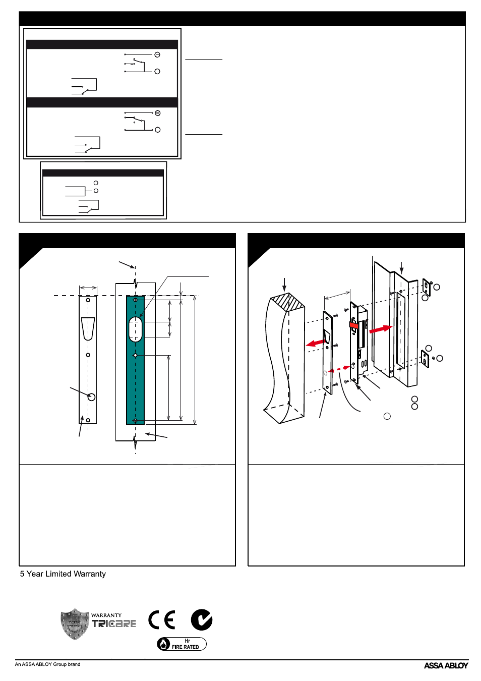
ELECTRICAL SPECIFICATION
Magnet
Line 3
D22 x 20 Deep
256
Strike Plate
3mm Thickness
7
48
242
24
132
27
Door
Line 1
(Half thickness of door)
4
• On the door, mark Line 3 corresponding to the top edge of the lock
faceplate
(step3)
• Mark and recess cutout of strike plate on door symmetrically, using
Line 1 as the centre guide and Line 3 as the height guide
• Cut out the 22mm wide and 20mm deep cavity for the bolt as
shown
above.
• Install the strike plate on the door, ensure the door gap is not more
than 8mm between the strike plate and the faceplate on the V-Lock
• Ensure strike plate is securely fastened to increase overall holding
force and security of installation.
Note: Thickness of strike plate - 3mm
DOOR PREPARATION AND INSTALLATION OF STRIKE PLATE
5
• Ensure all wiring connections are correct and are insulated, make
sure the wires do not rub on the any sharp edges or do not interfere
with any of the locking mechanism.
• Install the V-Lock into the door jamb as shown above
• Power up lock, then let the door open and close normally with door
closer. When the strike plate magnet comes within locking range, the
V-Lock will lock as long as the lock bolt closes within target locking
range (see Detail A)
INSTALLING VLOCK IN DOOR JAMB
Magnet and M must line
up for V-Lock to operate
Maximum door gap
8mm
Strike Plate
V-Lock Unit
Door Jamb
Door
M
Mounting Tabs (supplied)
Required for Flush
Mounting only
Mounting Nuts (supplied)
Required for Flush
Mounting only
Face Plate
1
2
1
2
1
2
ASSA ABLOY Australia Pty Ltd, 235 Huntingdale Rd, Oakleigh VIC 3166, Australia, www.assaabloy.com.au
ORANGE
BLACK
BLUE
RED
PURPLE
WHITE
- 0 volts d.c.
- Access Control (PTO)
- Positive Continuous Supply
- (COM)
- (NO)
- (NC)
Power To Open (PTO) Wiring Connections
DC Power
NC
NO
+
Bolt Position
Monitor
- Access Control (PTL)
ORANGE
BLACK
BLUE
RED
PURPLE
WHITE
- 0 volts d.c.
- Positive Continuous Supply
- (COM)
- (NO)
- (NC)
Power To Lock (PTL) Wiring Connections
DC Power
NC
NO
+
Bolt Position
Monitor
3 Wire Control
Bolt Position
Monitor
Power To Lock 2 Wire Control - NOT RECOMMENDED
ORANGE
BLACK
BLUE
RED
PURPLE
WHITE
- 0 volts d.c.
- (COM)
- (NO)
- (NC)
-
+
DC Power
2 Wire Control
ACCESSORIES AVAILABLE:
• ES8000 Glass Door Kit
• Strike plate with magnet
• Mounting bracket for high security applications
DA0076, ES8000 Datasheet, Issue 9, January 2010
2
ASSA ABLOY Australia guarantees the product for a period of 5 years in accordance with the
standard TRICARE warranty against defects in manufacture, workmanship or materials,
provided that all electrical and mechanical installation requirements are adhered to as per this
datasheet. All third party and consequential claims are expressly excluded from the warranty.
N13900