Trimec ES6000 Hook Lock User Manual
6000 series hook lock, 6000 series, Installation instructions
IMPORTANT NOTE: Ensure any rebate strips or door stops are fi tted before proceeding. Hook lock must NOT be used as the only form of door
stop.
This product had been designed for use in weather protected areas, and is NOT suitable for use in hazardous (fl amable or
explosive) atmospheres.
Do NOT attempt to change the locking mode as the unit had been factory set for maximum product reliability.
INSTALLATION INSTRUCTIONS
6000 SERIES HOOK LOCK
Remove cover screws and cover from hook lock.
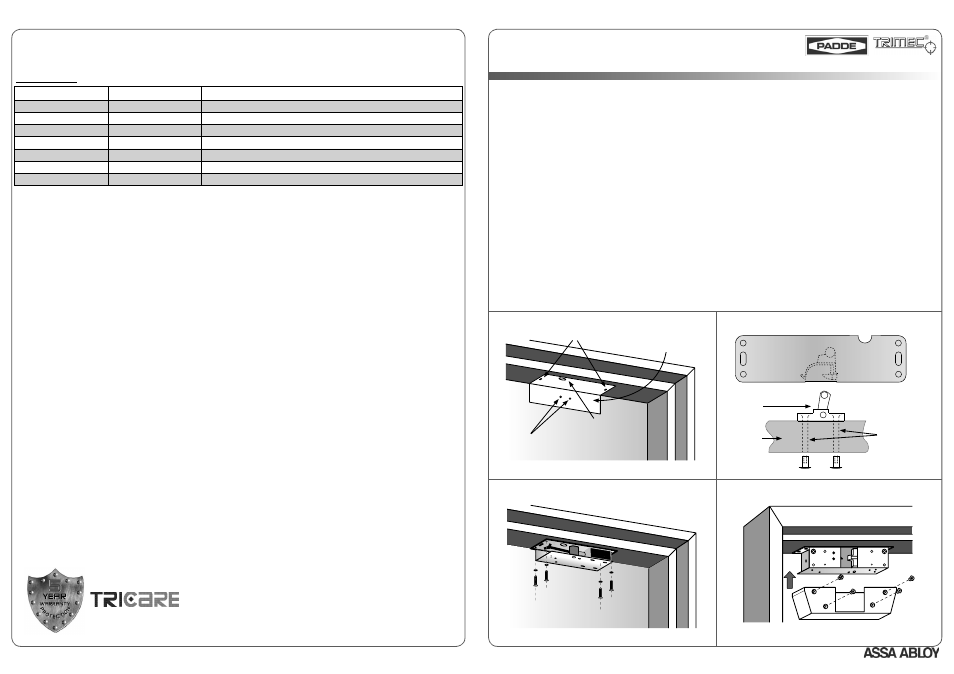
Use cardboard template supplied to mark the position of two elongated lock mounting holes in the door frame, wiring access hole and
two mounting holes for the striker on the door (see Fig. 1). The lock should not be fi tted within 20mm of any corner.
Using the wiring diagram provided on lock body or the datasheet, ensure all wiring is correctly connected and not rubbing on sharp edges
or interfering with any lock mechanism.
Using ONLY the two elongated holes in the lock body, fi x hook lock to door frame using the 6G self-tapping screws and washers provided.
Ensure that lock hook is facing the door.
Fix striker to door as per orientation shown in Fig. 2. Use
ø
9mm mounting holes for wooden doors;
ø
11mm mounting holes for metal
doors.
Allow the door closer to latch the lock by fi rst holding the door with the striker resting on the lock hook, and then releasing it. Adjust the
lock position until striker engages hook lock repeatedly without assistance.
Check that hook lock functions with power supplied. Lock should still latch freely under minimum closer force.
Mark and drill the remaining four fi xing holes for the lock before securing the lock in its permanent position (see Fig. 3).
Fit cover to lock body, then recheck that door opens and closes smoothly (see Fig. 4). Ensure that wiring is not trapped or pinched by
cover.
1.
2.
3.
4.
5.
6.
7.
8.
9.
Surface Mount Installation
Page 1
DRAWINGS NOT TO SCALE. INFORMATION IN THIS DATASHEET MAY BE CHANGED WITHOUT NOTICE.
Page 4
6000 SERIES
SPARE PARTS & ACCESSORIES
The following are available as optional extras:
SPARE PARTS
Part Number
Qty Per Pack
Description
206000-010
1
Silver Spare Cover
206000-011
1
Green Spare Cover
206000-012
1
Bronze Spare Cover
206000-013
1
Brown Spare Cover
206000-014
1
Black Spare Cover
206000-020
1
Screw Kit
206000-030
1
Roller Strike Kit
5 Year Limited Warranty
ASSA ABLOY Australia guarantees for a period of 5 years in accordance with Trimec’s Standard Warranty Conditions, against defects in
manufacture, workmanship or materials, provided that all electrical and mechanical installation requirements are adhered to as per this
datasheet. All third party and consequential claims are expressly excluded from this warranty.
warranty
An ASSA ABLOY Group brand
DA0095, Issue 2: 27th Feb 2007
ASSA ABLOY Australia
2/16 Atkinson Road
Taren Point 2229
NSW, Australia
www.trimec.com.au
Fig. 3 - Drill Fixing Holes, Secure Lock in Permanent Position
Fig. 1 - Mark Mounting and Wiring Holes with Template Provided
Striker Mounting Holes
Lock Mounting Holes
Wiring Access Hole
Template
Fig. 4 - Fit Cover to Lock
TRIMEC
TRIMEC
Fig. 2 - Fit Striker to Door in Orientation Shown
Drill
ø
9mm in
WOODEN door
OR
Drill
ø
11mm in
METAL door
Roller
Striker
Door