Trimec ES8000 V-Lock User Manual
Es8000 v-lock, Warning, Installation instructions
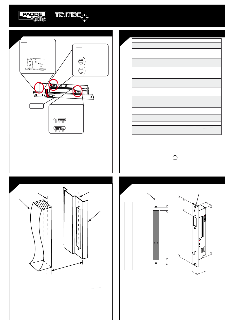
DOOR JAMB PREPARATION
42
30
M
Lock
Faceplate
256
15
15
30
256
50
24
210
Door Jamb
Line 2
ES8000 V-LOCK
WITH 30MM FACEPLATE
INSTALLATION INSTRUCTIONS
SELECTING THE MODE CONFIGURATION
STEP 1
- Loosen both screws on side of lock
body.
- With some force, slide screws in direction
required until stop at end of slot is reached.
- Hold in position and re-tighten screws.
PTL
PTO
STEP 3
- Change jumper position on Printed
Circuit Board beneath the red
re-sealable sticker as shown below:
Power-to-Open
(Fail Secure)
Power-to-Lock
(Fail Safe)
STEP 2
- Rotate Latch Plate screw beneath
the red re-sealable sticker according to
orientation shown below:
Turn counter-clockwise
180
o
for Power-to-Open
(Fail Secure)
Turn clockwise 180
o
for
Power-to-Lock (Fail Safe)
WARNING!
•
Lock mode configuration set to Power To Lock (Fail Safe). Ensure the correct
mode is set before applying power: you may be charged for incorrect
installation.
• Discard Bolt Label once correct mode is selected.
• If the lock had been installed or previously operated, the latch plate
screw (STEP 2) will not be visible. To change lock mode configuration,
contact your distributor for additional information.
• Ensure all re-sealable stickers and screws are re-attached after configuration
to prevent ingress of dust.
• V-Lock must ONLY be used in weather protected areas.
• V-Lock can ONLY be installed vertically or horizontally ABOVE the door
(not on or under the floor).
• V-Lock WILL NOT operate without strike plate. Strike plate MUST be
correctly aligned and in front of the M logo on the faceplate.
DOOR PREPARATION FOR STRIKE AND JAMB
2
1
Door
Door Jamb
Maximum door gap 8mm
• Before starting with the installation make sure the gap between the
door and the door jamb does not exceed 8mm
• Mark Line 1 corresponding to mid-plane of Door
• Mark Line 2 corresponding with Line 1 on the Door Jamb
Note: Make sure the Line 1 and Line 2 are aligned when the door is in
the closed position.
3
•
Mark cutout of V-Lock symmetrically about Line 2.
• Cutout size for faceplate must be 256mm x 30mm
• Prepare door jamb appropriately as shown.
Note: Thickness of faceplate - 3mm
Line 2
Line 1
Parameter
Specification
Door Gap
Ideally 3mm to 8mm only. 8mm maximum.
Lock Monitor Output
Voltage free changeover switch contacts rated for
48VDC / 100mA
Holding Force
AS4145.2 - 1993: Passed S3 (611kg for 1 minute)
Capable of 1000kg if strike plate is fully supported
Release under Side Load
15kg max at bolt with motorised unlocking (3 wire control)
3kg max at bolt with Power-To-Lock (Fail Safe) unlocking
and 2 wire control
Bolt Dimensions
Diameter = 11mm
Projection = 20.5mm
Power Supply (12-24VDC)
Regulation better than +/- 2%
1Amp Power supply required
Current Draw
Power to Lock holding current 130mA
Power to Open holding current 30mA
Initial locking and unlocking current draw higher
Misalignment tolerance
+/- 3.5mm
Operating Temperature
-10oC to +50oC at 90% RH
Durability
> 300,000 cycles
Certifications
SPECIFICATIONS AND NOTES
DRAWINGS NOT NOT TO SCALE. INFORMATION IN THIS DATASHEET MAY BE CHANGED WITHOUT NOTICE.
DRAWINGS NOT NOT TO SCALE. INFORMATION IN THIS DATASHEET MAY BE CHANGED WITHOUT NOTICE.
Bolt Label
•Up to 2-hour fire rating depending on doorset used, in accordance with
AS1905.1 - 1997, Part 1: Fire Resistant Doors
•CE compliant
•SCEC endorsed (high security strike bracket required)