Trimec ES2000 Series Monitored Electric Strike User Manual
Page 2
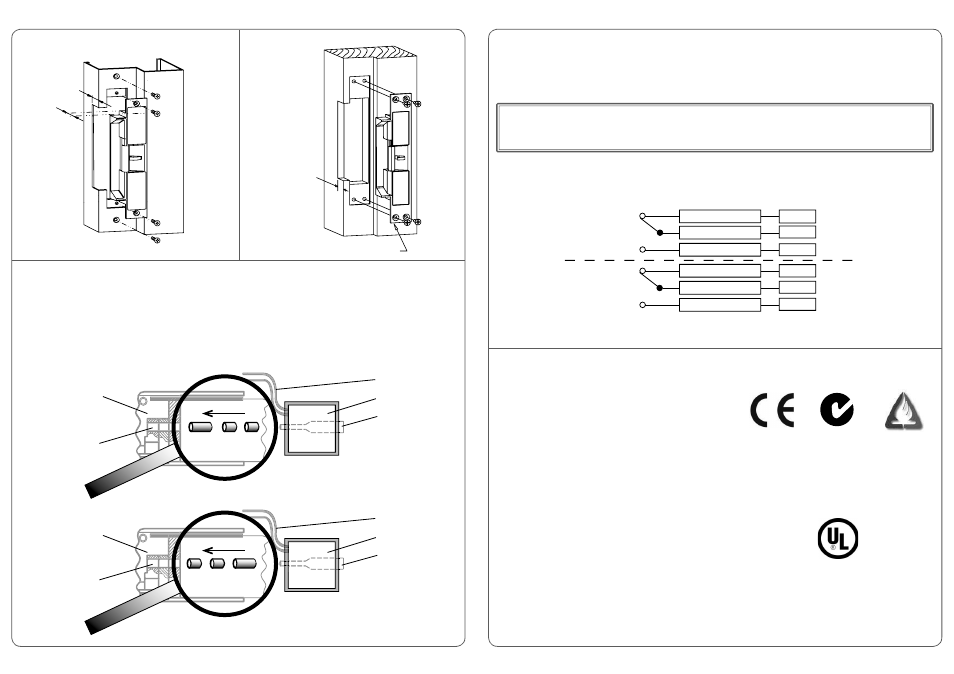
To change the electric strike’s mode of lock operation, remove the back cover and the 2 screws securing the solenoid.
Remove solenoid from strike housing, and invert the strike. This will release three locking pins from the strike and keeper chambers.
CAUTION! When removing solenoid, please be mindful to keep the plunger in the solenoid as it is not secured, and may be easily mis-
placed.
Re-insert the pins as shown in the diagrams for desired mode of lock operation (Power to Open: see Fig. 5; Power to Lock: see Fig. 6).
Place solenoid back in strike housing, and secure with solenoid screws. Press strike back cover into position.
1.
2.
3.
4.
Page 2
Page 3
Solenoid Leads Colour
Red
Blue
Black
Supply Voltage
12 VDC
24 VDC
48 VDC
Current Draw
175 mA
88 mA
45 mA
CAUTION!
Incorrect supply voltage may cause damage not covered by warranty. Please check supply voltage with a suitable meter
to ensure it is within +/- 15% of the nominal voltage shown above with the strike powered.
This product has been designed for use in weather protected areas only. DO NOT OIL OR LUBRICATE.
2000 Series Microswitch Monitoring
The 2000 Series electric strike is fi tted with a UL approved changeover microswitch (max. rating: 125 VAC, 3 A / 60 VDC, 200 mA) to monitor
the latch and strike status. The wiring diagram for the monitoring schematic is shown in Fig. 7 and on the back of the strike.
N.C. (Normally Closed)
Common
N.O. (Normally Open)
White
Orange
Grey
Strike
Common
N.O. (Normally Open)
Yellow
Violet
Brown
Latch
N.C. (Normally Closed)
Fig. 5 - Power To Open (Fail-Secure) Confi guration
Fig. 6 - Power To Lock (Fail-Safe) Confi guration
Certifi cation
AS4145.2 compliant
BS5872 approved
CE compliant
up to 4-hours fi re rating, depending on type of doorset
(in accordance with AS1905.1 - 1997, Part 1: Fire-resistant Doorsets)
Wiring methods and materials shall be in accordance with the National Electric Code, ANSI/NFPA 70 - 1996
Unit must be powered by a UL listed limited energy power source
Use only those mounting screws and hardware supplied with the product for installation. Do not use substitute installation fasteners or
hardware
UL listed for burglary resistance category 1034
Standard UL 1034 Tested and Listed for:
1,500 lbs. (680 kg) static strength rating
70 foot-lbs. dynamic strength rating
250,000 cycles endurance rating
At the request of ASSA ABLOY Australia, this model was tested to the following VOLUNTARY ratings:
1,000,000 cycles of operation
•
•
•
•
•
•
•
•
•
•
•
•
4
Hour
UL Listing
Solenoid
Plunger
Solenoid Leads
Strike Body
Locking Pins
(Long - Short - Short)
Pin Chamber
Locking Pins
(Short - Short - Long)
Solenoid
Plunger
Solenoid Leads
Strike Body
Pin Chamber
CHANGING MODE OF LOCK OPERATION
ELECTRICAL SPECIFICATIONS
Fig. 3 - Metal Jamb Installation
Fig. 4 - Wood Jamb Installation
Fig. 4 - Wood Jamb Installation
26mm
24mm
Fig. 7 - Monitoring Schematic
Fig. 7 - Monitoring Schematic
24mm
2400 series
strike shown