Timeguard SLFM360L User Manual
Page 3
2
3
A
C
B
Lens Mask
Less sensitive
Mor
e sensitiv
e
360
0
Side View
Top View
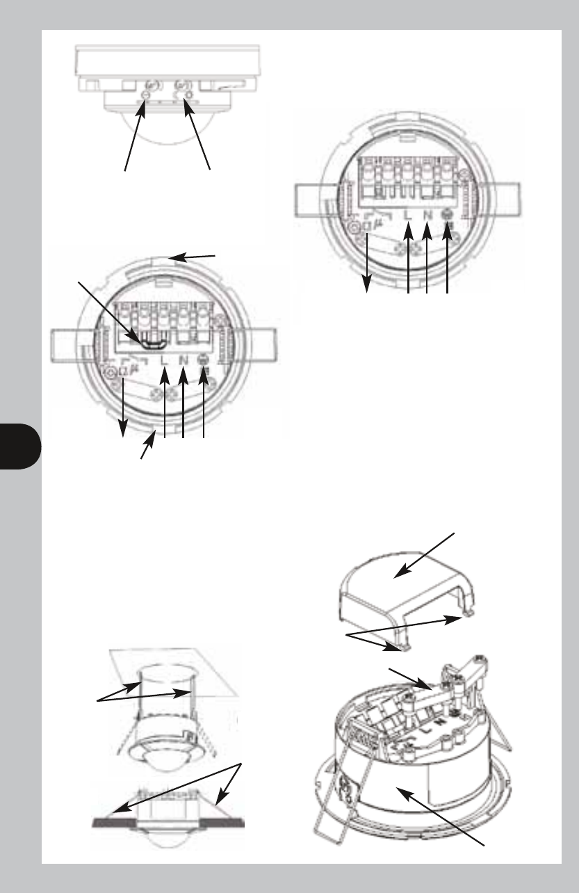
Wiring cover
Factory fitted
bridge wire
REMOVED
L1
L N E
Switched
Load
OUT
Factory fitted
bridge wire
Levering area
Time On
setting
Lux -
Dusk/Dawn
setting
Mains
Supply
IN
2.5m
6m
Cable clamps x2
Locators
L
ocating
springs
pulled
back
L
ocating
springs
fitted
position
Sensor
Levering area
D
E
F
G
Restrict long
detection
Restrict
short
detection
Restrict
detection
directly
under
sensor
L1
L N E
Switched
Load
OUT
Mains
Supply
IN
A
C
B
Lens Mask
Less sensitive
Mor
e sensitiv
e
360
0
Side View
Top View
Wiring cover
Factory fitted
bridge wire
REMOVED
L1
L N E
Switched
Load
OUT
Factory fitted
bridge wire
Levering area
Time On
setting
Lux -
Dusk/Dawn
setting
Mains
Supply
IN
2.5m
6m
Cable clamps x2
Locators
L
ocating
springs
pulled
back
L
ocating
springs
fitted
position
Sensor
Levering area
D
E
F
G
Restrict long
detection
Restrict
short
detection
Restrict
detection
directly
under
sensor
L1
L N E
Switched
Load
OUT
Mains
Supply
IN
In the above illustration:
• 4 core cable may be used
• There is no external junction box
• A bridge is provided, pre-wired to
bridge across live supply from
AC mains to the output load
via the contacts.
In the above illustration:
• The L1 L2 terminals are used to
control a DC load or if the load
uses a different phase or voltage
supply from the AC mains in.
• Factory fitted bridge must be
removed to isolate L1 & L2
terminals from AC mains in.