Timeguard SLW360L User Manual
Page 3
2
3
A
C
B
D
Lens Mask
Less sensitive
More
sensitive
Restrict short detection
360º
Mounting hole
Mounting hole
Side View
Side View
Restrict long detection
Restrict detection directly under sensor
E
F
H
G
I
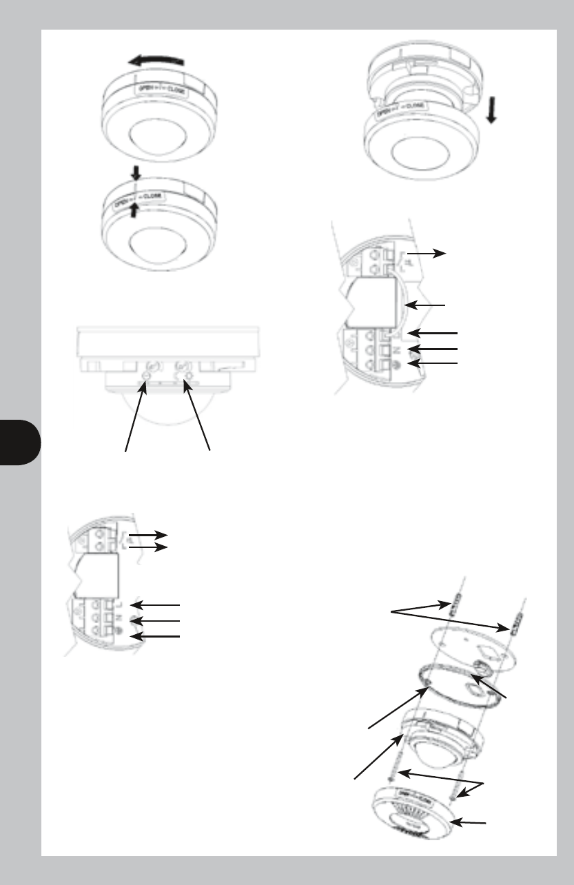
Twist cover anti-clock wise
Align marks on moulding
Remove decorative cover
Cable
gasket
Mounting
screws
Top cover
Ceiling mount assembly method.
L1
L1
L2
L
N
E
L
N
E
Switched
Load
OUT
Switched
Load
OUT
Factory fitted
bridge wire
Factory fitted
bridge wire REMOVED
Time On
setting
Lux -Dusk/
Dawn
setting
Mains Supply IN
Mains Supply IN
Sponge gasket.
Fit if mounting
the unit outdoors.
Discard if fitting
indoors
Mounting
Plate
Sensor
2.5m
6m
Wall plugs x 2.
A
C
B
D
Lens Mask
Less sensitive
More
sensitive
Restrict short detection
360º
Mounting hole
Mounting hole
Side View
Side View
Restrict long detection
Restrict detection directly under sensor
E
F
H
G
I
Twist cover anti-clock wise
Align marks on moulding
Remove decorative cover
Cable
gasket
Mounting
screws
Top cover
Ceiling mount assembly method.
L1
L1
L2
L
N
E
L
N
E
Switched
Load
OUT
Switched
Load
OUT
Factory fitted
bridge wire
Factory fitted
bridge wire REMOVED
Time On
setting
Lux -Dusk/
Dawn
setting
Mains Supply IN
Mains Supply IN
Sponge gasket.
Fit if mounting
the unit outdoors.
Discard if fitting
indoors
Mounting
Plate
Sensor
2.5m
6m
Wall plugs x 2.
In the above illustration:
• 4 core cable may be used
• there is no external junction box
• A bridge is provided, prewired
to bridge across live supply from
AC mains to the output load
In the above illustration:
• The L1 L2 terminals are used to
control a DC load or if the load
uses a different phase or voltage
supply from the AC mains in.
• Factory fitted bridge must be
removed to isolate L1 & L2
terminals from AC mains in.