Timeguard LED400PIRB User Manual
Page 2
LED400PIRB.1 Instructs_147x105 1-6
31-05-12 10.14am
Prepared by Sally
1
2
3
4
5
6
1. Designated Use
• LED400PIR is an outdoor motion detector for automatic LED lighting control
• Suitable for installation on walls
• Simple plug in wall plate for easy & safe connection
• Suitable for a wide range of locations: corridors, gardens, staircases,
entrances, garages, outdoor parking areas etc.
Index :
Page 2
Contents, Tools required.
Page 3
Product dimensions.
Page 4
Installation procedure.
Page 5
Sensor detection range .
Page 6
Walk test & adjustment, Detector head adjustment.
Page 7
Knob settings.
Page 8
Lens masking.
Page 9
Lamp adjustment
2. Basic Safety Instruction
Danger of death through electric shock.
• Must only be installed by qualifi ed electricians.
• Avoid the metal parts of the device due to potentially high temperature.
• The device conforms to EN60598 for designated installation; IP55 in
accordance with EN 60529 and IEC62471 Photo biological safety of
• Designed for use in normal environments
• Intended for outdoor installation.
• Energy saving.
• Long LED bulb life.
Page 10 High temperature in lamp.
lamps and lamp system.
Test mode
90
90
0
2
Sec
2 sec
Detector Head Adjustment
The detector head can be panned 90 deg.
to the left and 90 deg. to the right.
Walk Test and Adjustment
The purpose of Walk Test is used to test and adjust the detection coverage of
LED400PIR under auto mode.
• Adjust the Time knob to “
T ”, then conduct a walk test as described in test
procedure.
Test procedure:
• Adjust the Time knob to “
T ”, (Lux knob can be “Sun” or Moon”).
• Walk across the detection area, once the detector is triggered and the lamp
will turn ON for 2 seconds.
Note walking direction when performing test.
* Do not use the adjuster knobs to turn
the detector head.
180°
12m
6m
1m
10
20
30
40
40
10
20
30
40
40
18
0
1.8
T
O 2.5 M
12 ME
TER
6 METER
0.5m
180°
Installation Advise:
As the detector responds to changes in temperature, avoid the following
situation:
• Pointing the detector towards objects with highly refl ective surfaces,
such as mirrors etc.
• Mounting the detector near heat sources, such as heating vents, air
conditioning units, lights etc.
• Pointing the detector towards objects that may move in the wind, such as
curtains, tall plants etc.
Detection Range:
LED400PIR: Recommended installation height is 2.5 meter above ground, the
maximum detection range about 12 meter and at the angle of about 180 deg.
WARNING
10
20
30
40
40
12 ME
TER
WARNING
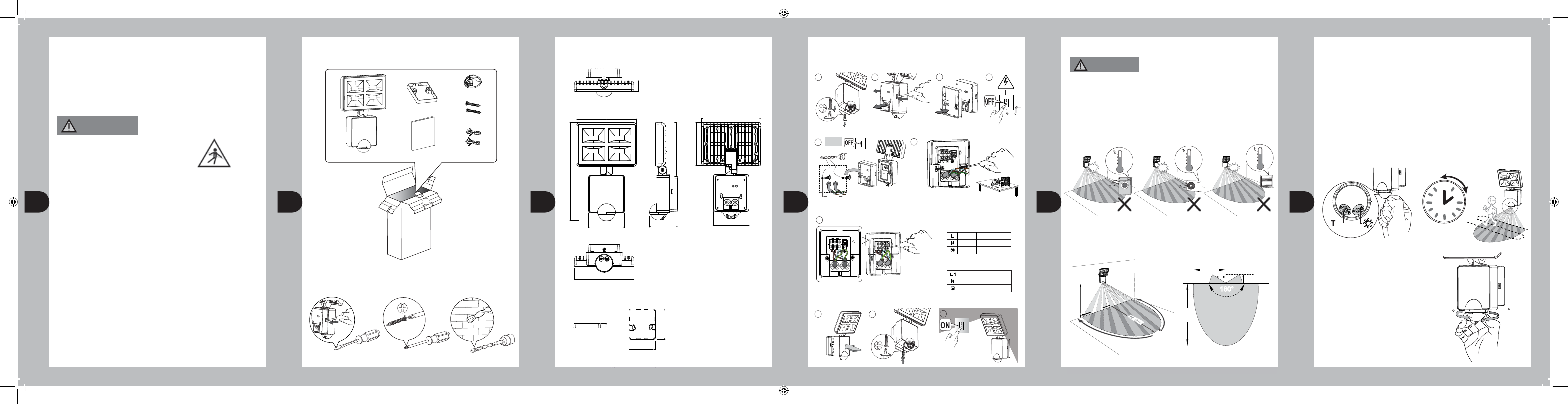
3. Contents:
What’s in the box?
4. Tools required:
X 1
X 1
X 1
Tools / Equipment need for installation.
INSTRUCTION
MANUAL
X 1
X 1
X 1
X 2
X 2
X 1
5. Product Dimensions:
179.00
131.00
108.00
161.00
86.00
179.00
292.00
108.00
31.00
179.00
Spacer dimension:
15.00
104.00
91.00
* The Spacer is an optional fitting
which gives maximum Pan angle.
2
5
3
1
4
6
7
MOUNTING SCREW x 2
φ 5mm
60mm
Fix the spacer
to the wall plate
- if required.
6. Installation Procedure:
Switch off
the power.
Screw the wall plate to the unit.
Unit goes into warm-up
period for 40 sec.
Connect the mains supply cable to the
terminal block on the backplate as follows.
For additional lighting, connect the external load
to the terminal box on the back plate as shown.
( See connection diagram )
CONNECTION:
LIVE
NEUTRAL
EARTH
BLUE
GREEN / YELLOW
BROWN
8
Feed the wires through rubber gasket of the wall plate with spacer and attach to
corresponding terminal.
Fix the spacer with the wall plate to the wall or the wall plate alone.
Attach the device
to the wall plate.
Unscrew the
wall plate.
240V
9
10
Use the spacer if necessary.
Push
CAUTION:
Push and open
the wall plate.
SWITCH LIVE
NEUTRAL
EARTH
BLUE
GREEN / YELLOW
BROWN