Energy saver floodlight 36 watts, Installation instructions, Cont – Timeguard ECO36F User Manual
Page 2: 3 year guarantee, Catalogue number: eco36f – black
For a product brochure please contact:
Timeguard Ltd. Victory park, 400 Edgware Road, London nW2 6nD Tel: 020-8452-1112
or email [email protected]
67.058.334 (Iss.1)
A Group company
For assistance with the product please contact the HELPLINE
on 020 8450 0515 or email [email protected]
3 Year Guarantee
In the unlikely event of this product becoming faulty
due to defective material or manufacture within 3 years
of the date of purchase, please return it to your supplier
in the first year with proof of purchase and it will be
replaced free of charge. For years 2 and 3 or any
difficulty in the first year telephone the helpline on
020 8450 0515.
This guarantee does not apply to the bulb.
Energy Saver Floodlight 36 Watts
Catalogue Number: ECO36F – Black
Installation Instructions
– cont.
The bulb supplied is a class B
(high efficiency) unit of 36W power
consumption giving a similar but
more diffuse light output to the
lower efficiency 150W halogen
units previously in use.
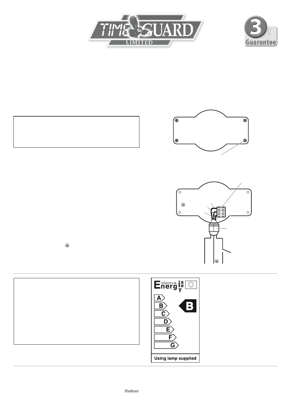
Wiring Instructions
Connection
Remove the wiring box cover by unscrewing the 4 retaining screws
(Fig. 4) and remove the cover being careful to retain the 4 screw
sealing rings and the cover gasket.
The unit is suitable for connection to a 230 V ac 50Hz electricity
supply. An isolating switch should be installed to switch the power
to the unit on & oFF. This allows the floodlight to be easily switched
off when not required.
Rotate the flood light so that the front glass looks back towards
the wall, giving good access to the connector block.
Take out the 2 screws holding the connector block in place and
remove the connector block to ease wiring.
Connect the mains supply cable to the terminal block as follows
(see Fig. 5 connection diagram):
nEUTRAL (Blue)
n
EARTH (Green/Yellow)
LIVE (Brown)
L
Ensure the connections are secure. Replace the connector block and
replace and tighten the 2 fixing screws. Adjust any excess cable and
tighten the cable gland. Refit the wiring box cover.
*** ImpOrtaNt ***
Switch off the electricity at the consumer unit
by removing the relevant fuse or switching off the
relevant circuit breaker before proceeding with
the installation.
Fig. 4
Fig. 5
WIrINg BOx COvEr
WIrINg BOx
CONNECtION dIagram
n (blue)
L (brown)
Connector
Block
4 x Retaining screws
Cable Gland
n
E
L
supply
Internal wall
switch/circuit
breaker
E
(yellow/green