Installation, Warning, Electrical shock hazard – ProMariner Combi Inverter Charger User Manual
Page 15
I n s t a l l a t i o n G u i d e l i n e s
26
25
Installation
I n s t a l l a t i o n G u i d e l i n e s
Installation
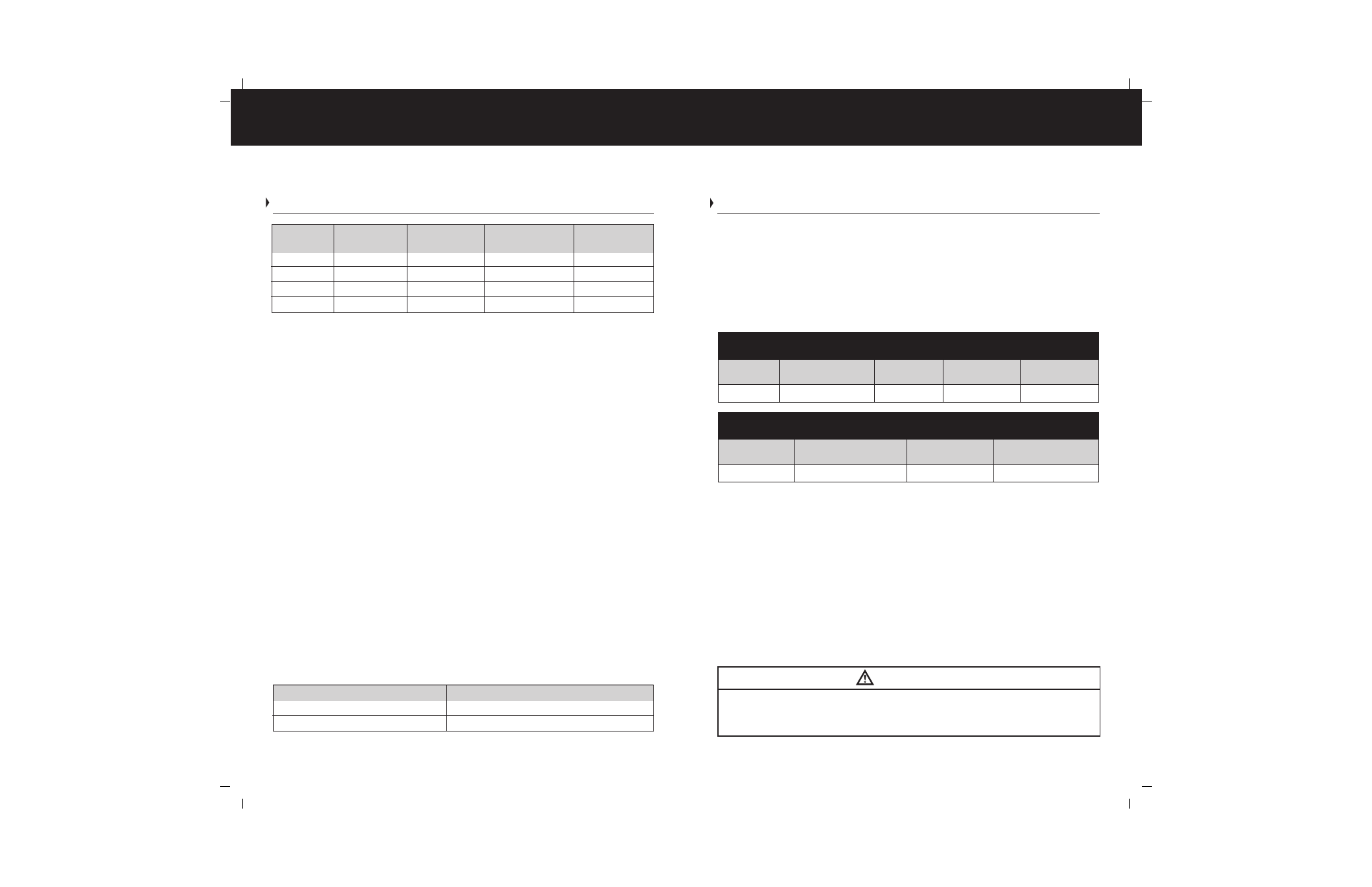
Inverter
12 Volt DC
24 Volt DC
Minimum Cable
Minimum Cable
Wattage
Amp Draw
Amp Draw
Size(AWG) 12V*
Size(AWG) 24V*
1000
100A
N/A
4
N/A
1500
150A
75A
2
6
2000
200A
100A
0
4
2500
250A
125A
00
4
b. Termination - Larger DC cables require specialty tools to ensure proper
termination with ring terminals. Pre-terminated cable kits can be
purchased through ProMariner or your local marine supply store. The
DC stud size is 5/16”. Cable type is as important as size. Cables must be
marine grade and acceptable under ABYC E-11 AC & DC Electrical
Systems on Board Boats (types such as UL 1426 Boat Cable, and SAE
J1127 Battery Cable are common and marked as such)
c. Connection – The ring terminal must be directly on the battery terminal
surface of the DC studs on the TruePower Combi, followed by the washer
and nut with a torque of 10-15 foot-pounds. The use of a dielectric or
anti-oxidant paste is recommended once the cables have been connected.
! DO NOT ATTEMPT CABLE TERMINATION BY MEANS OTHER THAN PROPER
CRIMPING, WITH A PROPERLY CALIBRATED TOOL. SOLDER AND AUTOMOTIVE
REPAIR TYPE BATTERY TERMINALS ARE NOT ACCEPTABLE. USE OF ANY OF THESE
TYPES OF TERMINATIONS WILL RESULT IN PREMATURE, UNWARRANTIED FAILURE
OF THE TRUEPOWER COMBI UNIT.
2) AC Cables – AC Cables should be UL 1426 Boat Cable, per ABYC E-11. This
type of cable is readily available in both 2 and 3 conductor. Size is based on
the maximum amperage to be passed through the cable and unlike DC does
not take into account the length of the cable run and voltage drop. The table
below indicates the proper size for AC Cables.
a. AC Connections – Screw terminals have been provided to connect
the input and output AC cables.
*Based on ABYC E-11 2008 Table VI-A Inside Engine Spaces.
Shore/station power Service
Cable Size (AWG) 105
° C Insulation
30 amp
12
50 amp
10
INSTALLATION MATERIALS – OVERCURRENT PROTECTION
(Fuses and or Breakers)
DC Cable Protection – The purpose of overcurrent protection is to protect the wire from
conducting too much amperage. Fuses and circuit breakers are adequate for this
purpose. The TruePower Combi is protected at the source for charging purposes
internally to the unit. The installer must provide overcurrent protection within 7” of the
point of connection to the positive terminal of the battery. The appropriate amperages
are provided below for both 12 and 24 volt models:
TERMINAL PROTECTION & STRAIN RELIEF
AC Terminals must be protected with the provided cover. This cover also includes grommets
to provide local strain relief on the conductors. The conductors shall also be secured to
structure within 18” of the unit by other means such as straps or wire ties.
DC Terminals must be protected with the provided covers. The covers allow for multi
directional cable installation and should be installed to match the direction of the
incoming cable. The conductors shall also be secured to structure within 18” of the
unit by means such as straps or wire ties.
MAIN PANELBOARD
A True RMS voltmeter must be installed on or in proximity to the main panelboard along
with the following label included with the TruePower Combi:
ANL Ignition Protected Fuses for TruePower Models 12V
Single Position
1000 Watt
1500 Watt
2500 Watt
ANL Fuse Holder
Amperage
100-425 amps
130 amp
175 amp
300 amp
ANL Ignition Protected Fuses for TruePower Models 24V
Single Position
1500 Watt
2500 Watt
ANL Fuse Holder
Amperage
100-425 amps
100 amp
175 amp
WARNING
Electrical Shock Hazard
Vessel is equipped with a DC to AC power inverter
Disconnect inverter DC input before servicing vessel’s electrical systems.