Connections, Installation – ProMariner Combi Inverter Charger User Manual
Page 14
I n s t a l l a t i o n G u i d e l i n e s
24
23
Connections
I n s t a l l a t i o n G u i d e l i n e s
Installation
AC IN
Marking
Description
Color
L
Line or Hot
Black
L2
Line 2 or Hot on 220 VAC applications only
Red
N
Neutral
White
G
AC Ground
Green or Green
w/ Yellow Stripe
AC OUT
Marking
Description
Color
L
Line or Hot. (Black). To 110 VAC powered
Black
appliances (main panelboard or split bus
or L1 loads on 220 VAC)
L2
Line 2 or Hot on 220 VAC applications only (Red).
Red
To 110 VAC powered appliances (main panelboard
or split bus or L2 loads on 220 VAC)
N
Neutral (White)
NOTE: This Neutral shall not be
White
connected to the ground other than at the designated
power source (e.g. TruePower Combi, Shore/station
power, generator) The internal transfer switch in this
unit maintains isolation until connected. Ensure that
existing transfer strategies do the same.
G
AC Ground
Green or Green
w/ Yellow Stripe
DC IN/OUT
Marking
Description
Color
+
Battery Positive = Positive Battery charge lead
Red
as well as power feeder for invert mode
-
Battery Negative = Negative Battery charge lead
Black or Yellow
as well as negative return for invert mode.
Earth
Safety Ground connected to the boats
Green or Green
DC grounding bus. This conductor is essential to
w/ Yellow Stripe
shock and fire prevention and carries current
as a result of a fault. AC Ground
! DO NOT OPERATE THIS UNIT WITHOUT THE EARTH CONNECTION ATTACHED.
The earth conductor is permitted to be 1 size smaller than the DC Positive (+) conductor
(Example: DC += 2 AWG, Earth = 4 AWG)
DC POWER SUPPLY
ProMariner Minimum Recommended Battery or Battery Bank is 200 Ahr.
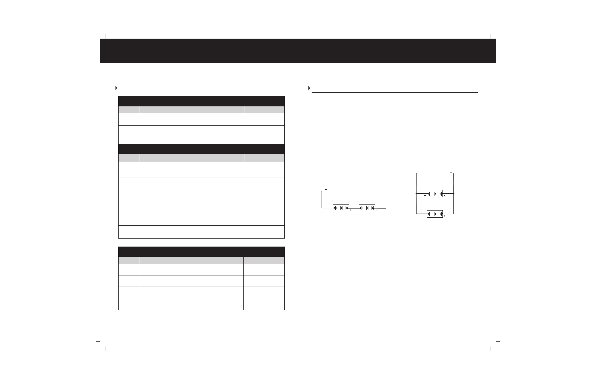
Series vs. Parallel - 2 types of battery connections exist; either installation can be used
with the TruePower Combi.
Series - Batteries connected in order to boost voltage while maintaining amp-hour ratings.
Parallel - Batteries connected in order to boost amp hours while maintaining voltage.
The two scenarios are easily illustrated:
INSTALLATION MATERIALS – CABELING
1) DC Cables - The DC portion of the TruePower Combi requires a large amount
of amperage in Inverter Mode. Cable size and length is of extreme importance
and should be well thought out and planned per this manual before
beginning installation. Items to consider are as follows:
a. Cable Size - Size is based on amperage draw of the unit compared
to the maximum amperage a cable can carry based on ABYC E-11.
ProMariner recommends NO MORE THAN a 10% drop in voltage from
source (battery) to the TruePower Unit or a cable run longer than 5 feet.
The following table outlines the cable size based on unit size.
Recommended Cable Sizes
(Based on UL 1426 105
° C Jacket Temperature Rating)
Series Batteries (12V)
for a 24V Bank
(Increases System Voltage)
Parallel Batteries (12V)
for a 12V Bank
(Increases the Amp/Hr Capacity)
12V Battery
12V Battery
12V Battery
12V Battery