Warning, Typical wiring configurations, Pronautic 12 – ProMariner ProNauticP User Manual
Page 5: 60 p, Preset-1 p reset-2, Caution
Battery Profiles
Charger Conditions
Charger Mode
Auto Maintain
Conditioning
Charging
AC Power
Auto Temp Control
Active PFC
Amps
Volts
SYSTEM DC OUTPUT LEVELS
Variable Speed Cooling
Self Test
Fault
OK
Standby
AUTO CONSERVATION MODES
100%
0%
Battery Health Program
Equalization
Charger Output
SETUP
ENTER
WARNING: HIGH VOLTAGE
ATTENTION : HAUTE TENSION
WARNING: LOW VOLTAGE
ATTENTION : BASSE TENSION
P
reset-1
P
reset-2
Flooded
Sealed
AGM
GEL
LiFePO4-Lithium
Calcium/Custom
Reverse Polarity
DC Volts Low
DC Volts High
Charger High Temp
Check Fan
Digital
ProMar
Performance Charging
1
2
3
AVOID SERIOUS INJURY OR DEATH FROM ELECTRICAL SHOCK. BEFORE OPENING
TURN OFF AC SUPPLY POWER. DO NOT EXPOSE TO RAIN OR SPRAY.
CHOC ELECTRIQUES PEUVENT PROVOQUER LA MORT OU DE SERIEUSE BLESSURES.
AVANT D'OUVRIR LA BOITE, COUPER LE COURANT. NE PAS EXPOSER AUX INTEMPÉRIES.
ELECTRICAL BURN AND SPARK HAZARD. BEFORE OPENING
DISCONNECT CHARGER CONNECTIONS AT BATTERIES.
(DANGER DE BRULURES ELECTRIQUE ET ETINCELLES). AVANT D'OUVRIR LA
BOITE DECONNECTER LES CONNECTIONS ENTRE CHARGEUR ET BATTERIE.
DISPLAY WAKE UP: Press any key; SELF TEST: Hold all keys 5 seconds
4
Warning
DO NOT attempt to install or operate the unit if it has been damaged in any way.
IMPORTANT NOTICE – PLEASE READ AND UNDERSTAND THIS MANUAL BEFORE
INSTALLING YOUR PRONAUTIC P SERIES CHARGER.
This manual is written to assist in the installation of your new ProNauticP Series Charger;
however, since this is a permanent AC and DC hardwired installation, ProMariner strongly
recommends that a Certified Marine Electrical Technician
®
trained by the American Boat and
Yacht Council (ABYC) perform the installation. The ProNauticP Series unit you have purchased
was constructed to the safety standards of the ABYC to prevent fire and electrocution; the
installation must conform to these same industry standards. For more information on ABYC,
their Standards and Technical Information reports for Small Craft and to find a certified
technician near you, visit www.abyc.com.
CAUTION:
To preclude a safety hazard, all existing AC and DC electrical components
(e.g. wire, fuses, circuit breakers, battery switches, and connections) must be inspected for
proper condition prior to installation. Failure to confirm adequate condition and proper
installation to ABYC standard E-11 AC & DC electrical systems on board boats may result
in a dangerous condition and/or premature failure of this or other installed electrical components.
Any and all areas of the existing system that are found not in compliance with ABYC E-11
must be replaced prior to installation.
CAUTION:
If you are replacing an existing battery charger please disconnect the battery
charger output cables from the existing charger AND the battery(s). Do not use existing cables
if they are not in compliance with the sizes detailed in this manual. If you have any doubt
about your ability to fuse and wire this unit correctly PLEASE refer to www.abyc.com for a
list of certified electricians in your area that are qualified to perform this installation to the
ABYC standards.
Important Notice: FCC Class B Notification & International Standards Compliance
NOTE: This equipment has been tested and found to comply with the limits for a class B
digital device, pursuant to Part 15 of the FCC Rules. These limits are designed to provide
reasonable protection against harmful interference when the equipment is operated in a
commercial environment. This equipment generates, uses, and can radiate radio frequency
energy and, if not installed and used in accordance with the instruction manual, may cause
harmful interference to radio communications.
Designed, Constructed and Tested to:
UL 1236 SB, CSA C22.2-107.2, FCC Class B and CEC
EN60335-1/2-29, EN60335-2-29, EN61000-3-2, EN61000-3-3
Complies w/ ABYC A-31, AC Input Power Factor Corrected, Meets EN61000-302:2000 + A2:2005
27
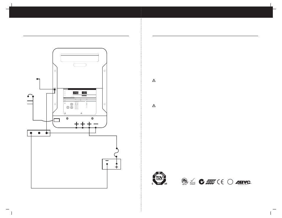
Typical Wiring Configurations
Typical Single12 Volt DC Common Ground Installation:
ProNautic 12
•
60 P
Power Factor Corrected & Global AC Input
DC Fuse
Main Grounding Bus
to Engine Negative
DC Charger Output
Case Ground
1 Size Smaller than the +
L
N
G
AC Input
12V Battery/Battery Bank
To Standards:
UL 1236 SB
CSA C22.2-107.2
Safety Certified by:
BC