Installation, Troubleshooting, Remote temperature sensor probe – ProMariner ProNauticP User Manual
Page 12
Installation
2. Fuse Selection - As illustrated in the diagram, each positive conductor from the charger to the
battery/battery bank must be fused. Choose a fuse that is 10 amps higher than the charger output
(e.g. 60 amps, choose a fuse of 70 amps). These fuses come in a variety of sizes and types. When
choosing the proper fuse consider the connection to the DC cable (inline types for smaller amperages,
stud and nut connections for larger amperages) as well as the availability of replacements. Fuses
and holders are available through ProMariner or your local marine supply store.
3. Ground - This is extremely important and often overlooked. There is one common battery
ground with the positive battery connections on the ProNauticP. There is also a “Chassis Ground”.
a. Battery Negative - As shown in the diagram, this is connected to a bus bar or terminal
stud (not included) that can handle, at a minimum the amperage of the charger output
(1260 = 60 amp minimum). This conductor shall be of equal size to the DC positive conductor
chosen above. The battery negative terminals are connected to this bus bar or terminal stud.
b. Bonding Stud A.K.A Chassis Ground - This stud is connected to the boats bonding system
as well as the bus bar or terminal stud mentioned above. This conductor is permitted to be
one size smaller than the DC positive conductor chosen above; in the case of a DC to the
case fault, this conductor is critical in carrying the fault current to trip the fuse or breaker,
the AC ground CAN NOT handle high DC amperages.
4. Empty Charger Banks - In the event of an empty charger bank there is no need to use a jumper as
done with traditional chargers. Simply leave the DC positive unloaded and the unit will perform correctly.
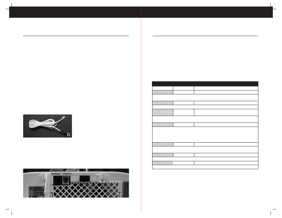
Remote Temperature Sensor Probe
11
20
Probe Connections:
Battery End (ring terminal) – Connect to the NEGATIVE terminal of the battery.
Charger End – Attach the “phone” style plug into the charger port labeled “BAT SENSE”.
Note: Once the temperature sensor is connected the charger will adjust its charge based on the
batteries temperature. This is known as thermal compensation, where the charger will cut back
if necessary to increase battery life. This is especially useful for AGM and GEL batteries which
are inherently temperature sensitive.
The ProNauticP comes standard with a
temperature probe that is plug and play. The
temperature probe must be connected while
the charger is powered down or before it is
connected to the breaker during installation.
For best performance, attach the probe to the
negative terminal of the “house” batter/bank
Troubleshooting
The ProNauticP includes advanced fault indication. Faults, if indicated, may require service
from ProMariner. For inquiries and service information Please call our Customer Care
Department line at 1-800-824-0524 from 8:30 am to 5 pm (Eastern Standard Time) for any
warranty, service or installation assistance you may need. Thank You
! THERE ARE NO USER SERVICEABLE PARTS INSIDE THE PRONAUTICP. DO NOT
ATTEMPT TO DISSASEMBLE THE UNIT. EVIDENCE OF DISSASEMBLY WILL VOID
MANUFACTURERS WARRANTY.
The first step to any problem is resetting the ProNauticP unit by turning off the AC breaker
providing power, waiting at least 10 seconds and turning it back on again.
Review the Operations section for the meaning of the fault indicator and suggestions on
how to clear the fault.
Charger Fault (Service) Conditions
LED Label
LED Color
Fault
Reverse Polarity
Red
Indicates a reverse polarity situation
Check DC Connections, ensure positive + (RED) and negative - (BLACK and/or YELLOW)
connections are attached accordingly
DC Volts Low
Amber
DC system voltage is less than 11.0 VDC
Bring system voltage over 11.0 VDC, check battery(s) condition and replace as necessary.
DC Volts High
Red
Indicates a high DC voltage from an outside source
such as a failed alternator
Using a multi-meter check alternator(s) output, generally over 15VDC. Determine if fault exists
in regulator or alternator, solar panel, wind generator etc. Replace as needed.
Charger High Temp Amber
Charger has shut down due to high temperature
Generally this indicates that the unit has been installed in an area with a very high ambient temperature.
This unit is designed for use in an engine room, if installed in an engine compartment; ensure that there
is proper ventilation in the space for the charger and other temperature sensitive components. If the
installation area temperature is 45° C (113° F) or more, move charger or add ventilation to lower ambient
temperature. The recommended maximum ambient temperature for installation is 45° C. (113° F)
Check Fan
Red
Fan failure
Ensure that the cooling fan can move freely and that no debris is blocking the fan movement.
Persistent fan problems require service from ProMariner.
Fault
Red
Indicates a fault
Please contact ProMariner for service options.
Auto Temp Control
Red flashing
High temp causes unit shutdown
See charger high temp above
Note: Installation is permitted in an environment of 45° C (113° F) and may result in output
of unit decreasing to protect the internal components and the performance of the unit.