Connection examples, Io-extension – sk tu4-ioe – NORD Drivesystems TI 275281106 User Manual
Page 5
IO-Extension
– SK TU4-IOE
TI 275281106 - 4912
5
Potential
Contact
Designation
Description
A
n
a
lo
g
I
O
s
1
VO 10V
10 V Reference voltage
2
VO 10V
10 V Reference voltage
3
AIN1+
Analog input 1, positive
4
AIN2+
Analog input 2, positive
5
AIN1-
Analog input 1, negative
6
AIN2-
Analog input 2, negative
7
AGND/0V
Analog Ground (internally connected to terminal 40)*
8
AGND/0V
Analog Ground (internally connected to terminal 40)*
9
AOUT
Analog Out
10
PE
PE
S
yste
m
b
u
s le
ve
l
a
n
d
d
ig
ita
l i
n
p
u
ts
11
VI 24V
Supply voltage (+24 V - in)
12
VI 24V
Supply voltage (+24 V - in)
13
VI 24V
Supply voltage (+24 V - in)
14
SYS +
System bus data cable +
15
GND/0V
Reference potential (0 V / GND)
16
SYS -
System bus data cable -
17
GND/0V
Reference potential (0 V / GND)
18
GND/0V
Reference potential (0 V / GND)
19
DIN1
Digital input 1
20
DIN3
Digital input 3
21
GND/0V
Reference potential (0 V / GND)
22
GND/0V
Reference potential (0 V / GND)
23
VI 24V
Supply voltage (+24 V - in)
24
VI 24V
Supply voltage (+24 V - in)
25
DIN2
Digital input 2
26
DIN4
Digital input 4
27
GND/0V
Reference potential (0 V / GND)
28
GND/0V
Reference potential (0 V / GND)
29
VI 24V
Supply voltage (+24 V - in)
30
VI 24V
Supply voltage (+24 V - in)
Di
g
ita
l
o
u
tp
u
ts
31
VI 24V2
Supply voltage (+24 V - in) for digital outputs
32
GND2/0V2
Reference potential (0 V / GND) of digital outputs
33
DOUT1
Digital output 1
34
DOUT2
Digital output 2
35
GND2/0V2
Reference potential (0 V / GND) of digital outputs
36
GND2/0V2
Reference potential (0 V / GND) of digital outputs
Di
a
g
n
o
stic
so
c
ke
t
RJ12 - 1
RS485_A
Data cable RS485
RJ12 - 2
RS485_B
Data cable RS485
RJ12 - 3
GND
Reference potential (GND)
RJ12 - 4
RS232_TxD
Data cable RS232
RJ12 - 5
RS232_RxD
Data cable RS232
RJ12 - 6
24 V
Supply voltage (+24 V)
* AGND/0V is internally connected to the reference voltage of the module GND/0V via a special
component. In order to prevent damage to the module or faults in the analog signals, the two
contacts must not be bridged
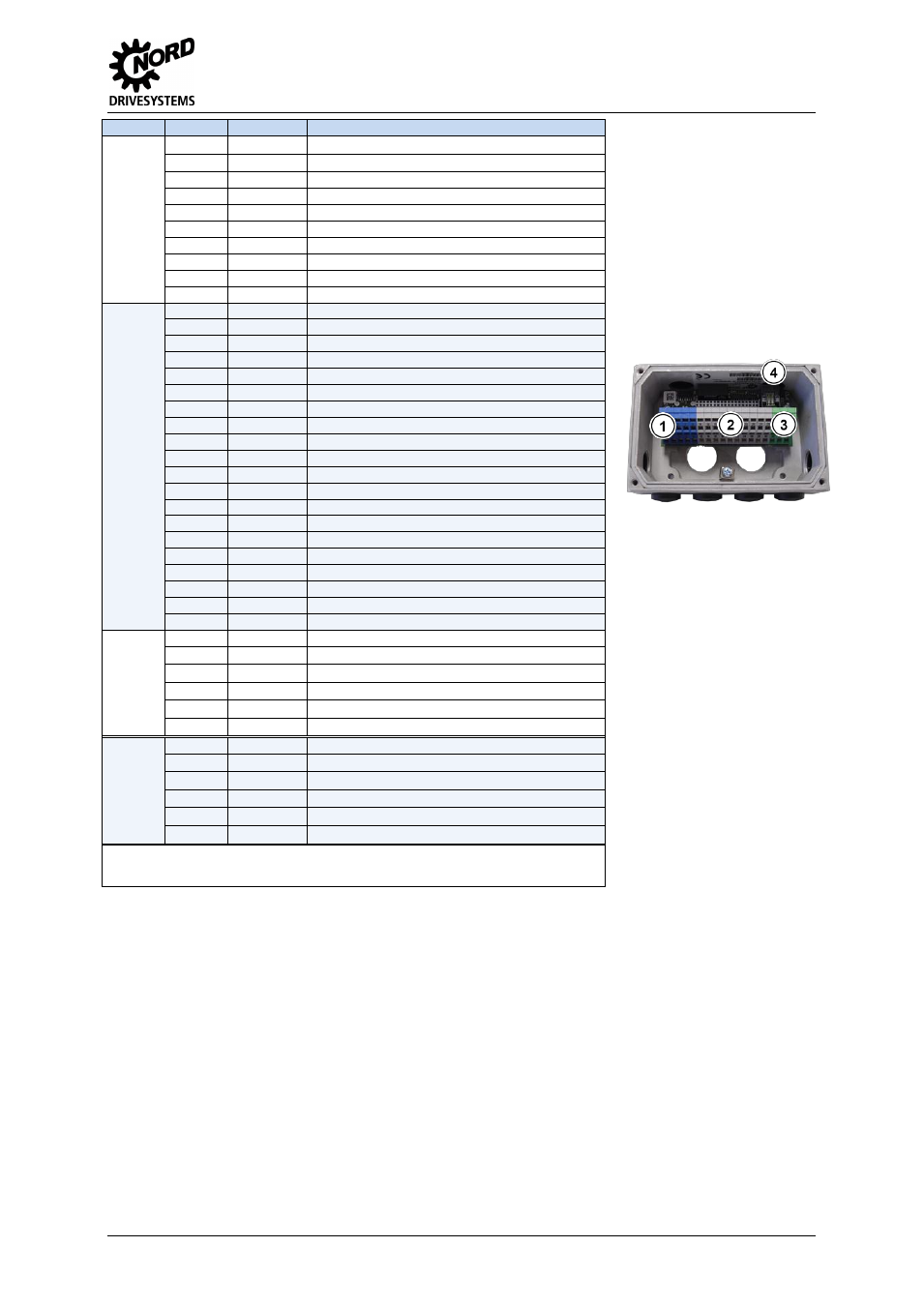
Potential level
1 =
2 =
3 =
4 =
Analog IOs
System bus + DIN
DOUT
Diagnosis
Pos : 12 /T echnisc he I nf ormati onen/I O - Er weit er ung/ Ans chl uss beis piel e [IO E Allgemei n] @ 2\ mod_1352736753713_388. doc x @ 51105 @ 6 @ 1
Connection examples
The following connection examples are generally applicable for NORD IO modules. The number or
type of the available IOs and their configuration on the terminal rail varies according to the module.
The actual availability or the designation of the individual contacts should be obtained by reference to
the description of the connections. The technical data (e.g. load capacity) must be taken into account.