NORD Drivesystems TI 18552095 User Manual
Technical information / datasheet, Notice, Level adapter pcb
Technical Information / Datasheet
Level adapter PCB
HTL - HTL A+/- B+/-
V1.0
Erstausgabe / first issue
4813
Rck
TI 18552095
GB
version
reason for change(s)
issue
name
document
speech
Pos : 2 /T ec hnis che Inf or mationen/ Zubehör/Pl ati ne_Pegel wandl er_C ontel ectg eber/Pl ati ne Pegel anpass ung HT L - HT L A+/- B+/- / 18552095 / Basisi nfor mati onen [ - HTL -HTL+/-] @ 4\ mod_1385464912683_388. doc x @ 106965 @ 555 @ 1
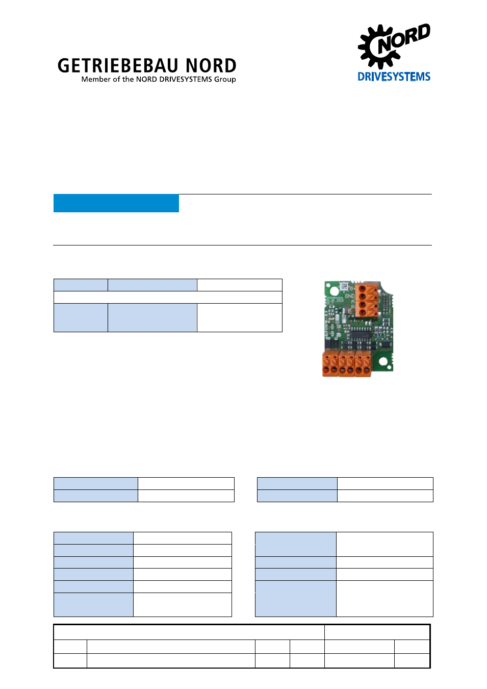
Level adapter PCB
HTL – HTL A+/- B+/-
Part number: 18 552 095
Level adapter HTL – HTL A+/- B+/-
NOTICE
Validity of the documents
This document is only valid in combination with the operating instructions for the relevant drive unit. All of the
information that is relevant for a safe start-up of this module and the drive unit is only available under these
conditions.
Scope of delivery
1 x
Module
PCB, lacquered
Accessories required
1 x
Mounting kit
OBW MOUNTING KIT
PCB 185520xxx
(Part No. 18552160)
Usage area
The module, which is intended for installation in the motor terminal box, is used to convert HTL or TTL
signals into complementary HTL signals. With this form of signal, the probability of errors in data
transmission is considerably reduced. Use of this module is recommended for cable lengths in excess
of 30 m.
Technical data
Module
Ambient temperature
-25°C … +75 °C
Weight
20 g
Protection class
IP00
Dimensions [mm]
L x W x H: 46 x 35 x 22
Electrical data
Electrical connection
Spring terminals
Cross-section
20-16 AWG
Input voltage
10 … 30 V DC
Connection terminals
(0.5 – 1.5 mm
2
)
Input level "0"
≤ 0.8 V
Power consumption
10 mA (own consumption)
Input level "1"
≥ 2.4 V
Max. frequency
100 kHz
Max. output voltage
= Input voltage
Max. cable length
500 m at 20 kHz
Typical output
current: 100 mA
dynamic: 200 mA