Pin out and connector assignements – Kaman KD-5100 User Manual
Page 17
17
9. PIN OUT and CONNECTOR ASSIGNEMENTS
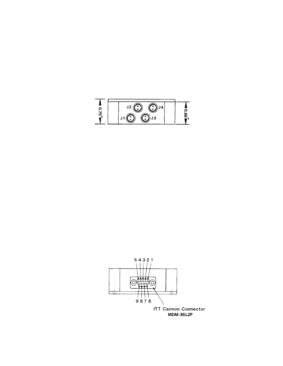
9-1. Sensor cable connections (Figure 10):
AXIS
CONNECTORS
SENSORS
1
J3 J1
S3 S1
2
J4 J2
S4 S2
Figure 10 Sensor Cable Connections
9-2. Pin assignments for the Power/Signal line connector J5 (Figure 11):
PIN
FUNCTION
1
+
15Vdc*
2
-
15
Vdc*
3
Power
Supply
Common
4
Signal
Output:
Axis
1
5
Return Signal for Pin 4
6
Signal
Output:
Axis
2
7
Return Signal for Pin 6
8
Not Used
9
Not Used
*Power
Requirements
Tolerance
+
15Vdc +1.0,
-0.5Vdc
-
15
Vdc +0.5,
-1.0Vdc
Figure 11 Power & Output Connections