Untitled, Flow chart, Instruction – FUTEK IPM500 (D500) Digital Display User Manual
Page 2: Default settings
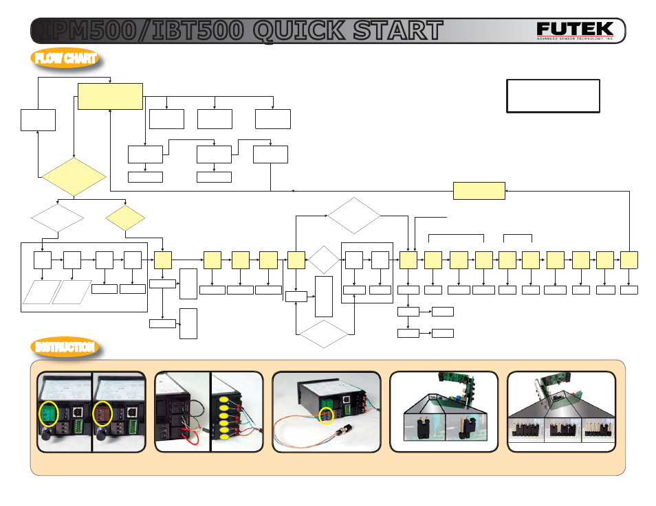
The
GREEN
/
BLUE
power connector
is for AC and the
BLACK
/
BROWN
is for DC.
The display can be connected to sen-
sors
rr with 6 wires or 4 wires.
Copyright 2007 Futek Advanced Sensor Technology, Inc.
FLOW CHART
INSTRUCTION
IPM500/IBT500 QUICK START
You may remove the tare switch (in-
cluded in std. package) from the back
and mount
it on your front panel.
Setting hardware lock out jumper.
1) T o move s ideways , pres s
ME NU
2) T o move down, pres s P E A K
3) F UT E K default s ettings in
red
Operation Mode
pres s 'P E AK ' to
toggle between
peak s ignal and
output s ignal
pres s 'R E S E T +
ALAR M' to res et
alarm conditions
pres s 'R E S E T +
P E AK ' to res et
peak value to
current
1s t 'ALAR M' pres s
s hows alarm
s etpoint #1
2nd 'ALAR M'
pres s s hows alarm
s etpoint #2
3rd 'ALAR M' pres s
returns to
dis played output
pres s 'P E AK ' to
change
pres s 'P E AK ' to
change
pres s 'ME NU' to
enter Menu Mode
pres s 'ME NU +
R E S E T ' at any
time to return to
Operation Mode
InP ut
S trn
dC u
20.0
50.0
100.00
250.00
500.00
20.0
50.0
100.00
250.00
500.00
S E tuP
00_15
C onF G
020_0
F iLtr
11100
If C onF G = 01000,
move to B lock #1 and
s kip B lock #2
If C onF G = 00000
Lo In
Hi In
Lo rd
reads
low input
s ignal
from
s ens or
reads
max input
s ignal
from
s ens or
99999
Hi rd
99999
B lock #1
dE C .P t
ddddd
0
.0
.00
.000
.0000
.00000
S E r 2
S E r 1
An Hi
An Lo
AnS E t
ALS E t
0011
15
1
99999
99999
00040
rE S E t
S cale
OF F s t
99999
00000
B lock #2
If S E tuP = 00
_15 and
C onF G = 00000, ins ert
B lock #1
here
If S E tuP =
00005, move
ahead to
B lock #2
V alues obtained
from C ertificate or
www.F utek.com
dev 1H
dev 2b
99999
99999
(Analog C ard Option)
(R S 232/485 Option)
(Alarm / R elay Option)
DEFAULT SETTINGS
INPUT:
STRN 20.0
SETUP: 00_15
FILTER: 11100
DECIMAL PNT: see label on instrument
HI & LO IN: 20.000 & 00000
HI & LO RD: 2000.0 & 00000
LOC 1: 00000
LOC 2: 0000
LOC 3: 0000
SER 1: 151
SER 2: 0011
SER 3: 00000
SER 4: 000
‘0’ for unlock
‘1’ for lock.
To lock the setup
menu, set ‘loc 1’ to
‘11111’. ‘0’ for unlock
and ‘1’ for lock.
Loc 2
Loc 1
0000
00000
-GAIN
Loc 3
0000
6 Wire Sensor
Connection
Locked
4 Wire Sensor
Connection
Changing the location of the jumpers
will change the excitation voltage.
+5VDC +10VDC
+24VDC
Jumper
Jumper
Unlocked
VAC Standard
VDC Optional
J1
J1
J5
INSIDE
INSIDE
-Exc
-Sen
-Sig
+Sig
+Exc
+Sen
AC (Green Connector)
85 to 264 VAC
DC (Brown Connector)
9 to 37 VDC
Tare Switch
Connection
11
(default)
00000