Dwyer instruments, inc – Dwyer SVE User Manual
Page 2
INSTALLATION
Warning: Before installation make sure all air pressure
has been released, electric power has been turned off,
and air pressure source has been closed. Turn power on
and increase pressure only after installation is completed.
LOCATION
Select a location that will not exceed the ambient temperature
specifications of the valve. The system must be located in an en-
closure that meets relevant safety standards and electrical codes
of the environment.
MOUNTING
1. Disassemble RSV solenoid valve by removing top nut and wash-
er. Remove solenoid body and finally remove lower nut.
2. Make a hole in the panel that is .76 to .81˝ (19.5 to 20.5 mm) in
diameter. (Panel thickness can be from .04 to.15˝ (1 to 4 mm)).
3. Place valve body/tube through the panel hole from the outside
and tighten down lower nut onto the body threads from the inside.
4. Replace solenoid and washer. Tighten down with top nut to hold
down the solenoid.
The RSV can be mounted in any position. For optimum life and per-
formance it is recommended that the unit be mounted vertically
and upright to reduce the chance of foreign matter accumulating in
the valve. For weatherproof applications it is recommended the
cable gland be positioned face down to avoid possible rainfall or
water from entry.
PNEUMATIC CONNECTIONS
Verify that the supply pressure is within the required specification.
Do not turn on the system before installation is complete. Make
sure that there is no dirt or other particulates between the RDCV
diaphragm valve and the connections of the RSV, remote solenoid
valve, which would cause a restriction of airflow. There should be
no condensed water in the piping. The use of a filter may be re-
quired to avoid this problem. Leak testing should be done prior to
installation only.
WIRING CONNECTIONS
Wire in accordance with the National Electrical Code and local reg-
ulations.
RSV
To aid in the wiring, the solenoid on the RSV may be rotated 360°.
Pre-wired models come standard with 22˝ (55 cm) of 18 AWG wire.
For unwired models it is recommended to use 18 AWG copper
wire rated at 90°C or greater.
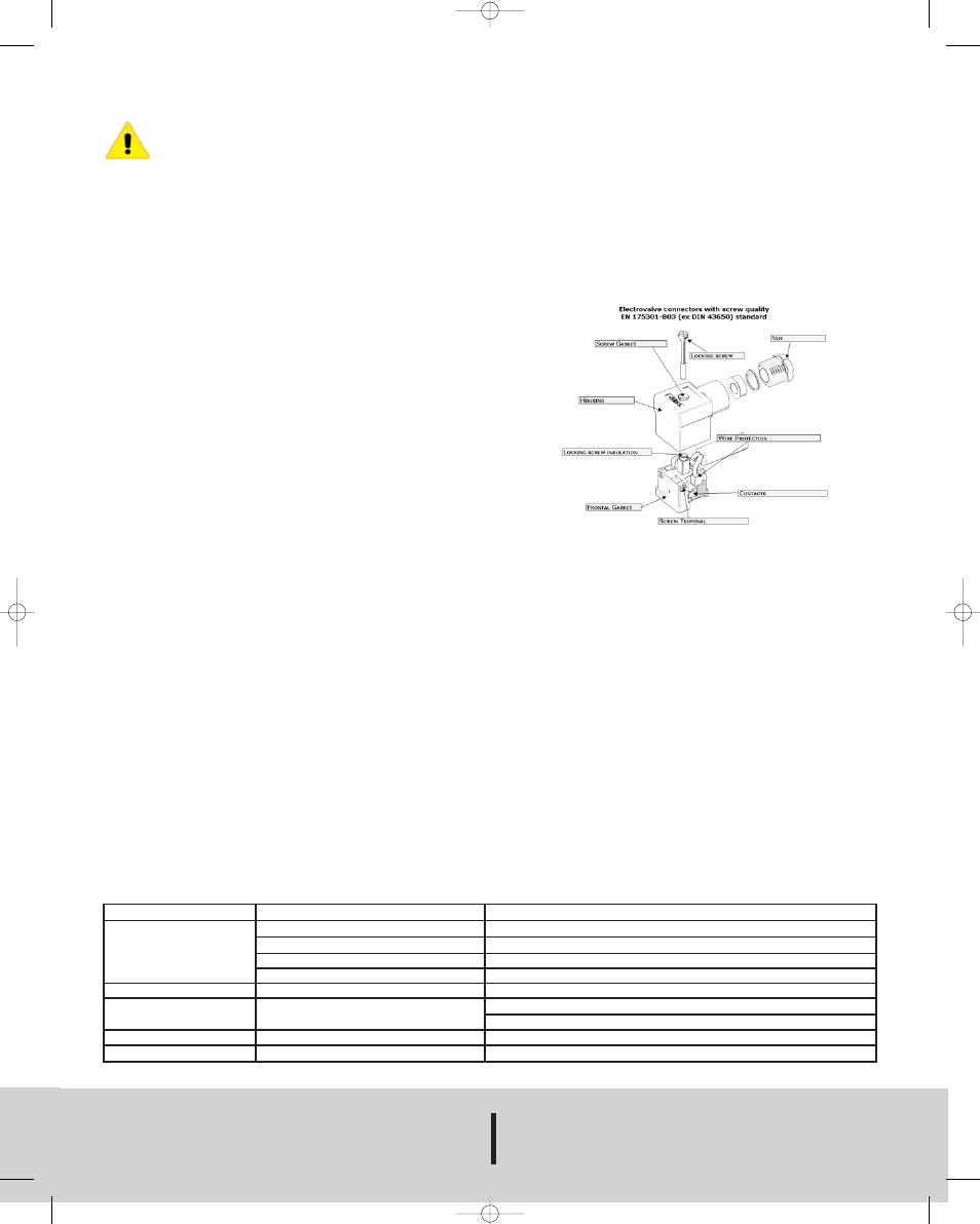
Wiring the RSV with DIN connector. See Figure 1.
1. Remove center screw and pull wiring assembly from the body.
2. Remove gasket and place small screw driver in slot to pry out
the terminal block from the cover.
3. Thread wire through the gland nut, gland gasket, washer and
connector cover.
4. Connect wires to proper terminals on the terminal block.
5. Snap terminal block back into the cover. The connector cover
may be rotated in 90° increments to position the cable entry as
needed for the application. Reinstall the center screw and screw
back into the solenoid body.
Wiring the SVE
The SVE comes from the factory with the RSV solenoids wired to
a terminal block. Connect 18 AWG copper wire rated at 90°C or
greater to the screw terminal block. Ground screw is provided on
the terminal block. The enclosure has a 3/4˝ NPT female conduit
connection. When wiring is complete reinstall cover making sure
that the gasket is in place. Tighten all screws in a crisscross man-
ner.
MAINTENANCE
Warning: To prevent the possibility of death, serious injury or prop-
erty damage, turn off electrical power, depressurize system and
unit, and vent fluid to a safe area before servicing.
The RSV should be cleaned periodically. The amount of time be-
tween cleanings depends on the application. Preventive Mainte-
nance includes keeping media clean of material and oil free, and
periodic testing to insure proper operation and to look for wear or
damage.
WARRANTY
Upon final installation of the Series RSV Remote Solenoid Valve
and the Series SVE Solenoid Valve Enclosure, no routine mainte-
nance is required. A periodic check of the system calibration is
recommended. The Series RSV and Series SVE are not field ser-
viceable and should be returned if repair is needed (field repair
should not be attempted an may void warranty). Be sure to include
a brief description of the problem plus any relevant application
notes. Contact customer service to receive a return goods autho-
rization number before shipping.
©Copyright 2005 Dwyer Instruments, Inc.
Printed in U.S.A. 12/05
FR# R2-443335-00
DWYER INSTRUMENTS, INC.
Phone: 219/879-8000
www.dwyer-inst.com
P.O. BOX 373 • MICHIGAN CITY, INDIANA 46361, U.S.A.
Fax: 219/872-9057
e-mail: [email protected]
Problem
No pulse
Leakage in outlet port
Low pulse
Shaking noise
Solenoid noise
Possible Cause
No supply air
Air pressure is too high
No voltage to RSV
Solenoid is damaged
Improper installation of inlet port
Low air pressure
Valve screws are loose
Solenoid mounting screws are loose
Action Required
Check whether the air compressor and valve have been turned on
Check the pressure of the air supply
Check supply voltage
Send back for evaluation
Check the pipe connections between the inlet and outlet
Check air supply pressure
Verify that the air supply was distributed properly
Tighten the loose screws
Tighten the loose screws
Solenoid Valve Troubleshooting
Figure 1
RSV 12/16/05 10:43 AM Page 2