Dwyer 285 User Manual
Page 6
Auto Calibration and Basic Operations
Buttons Operations
Series 185 and 285 positioners perform various functions using four buttons. The
position of the buttons is shown below:
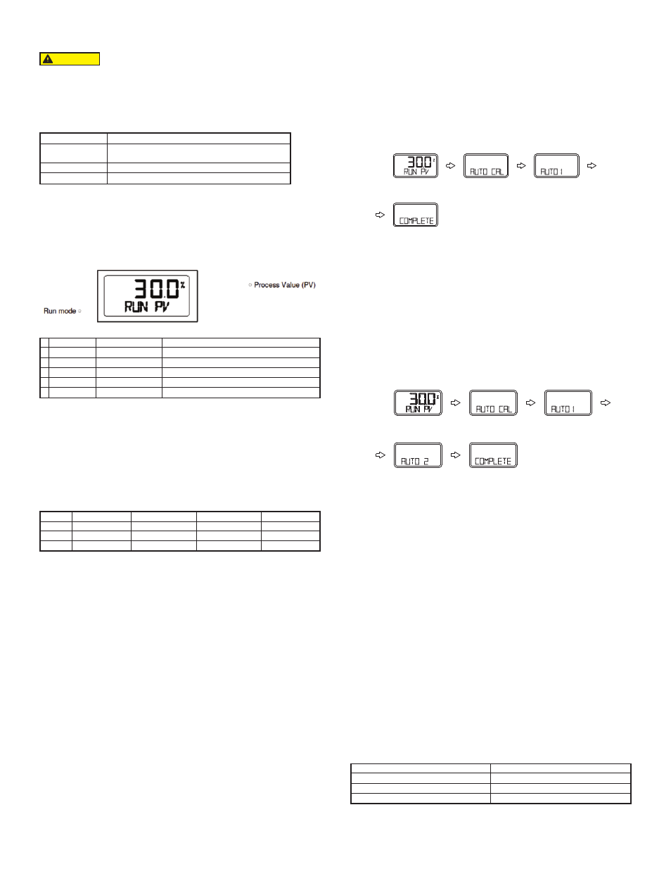
RUN mode
After connecting the power to the positioner, the following is displayed on the LCD
in 6 seconds.
RUN on the bottom line means that the Smart Positioner adjusts valve stroke based
on an outside signal (4 to 20 mA) and PV refers to the number on the LCD. In RUN
mode, valve stroke is changed according to input signal.
First Auto Calibration
First auto calibration is usually used when the positioner has not been set, such as
the initial setting with valve at the valve company, or replacement with other product
in the field. In this case, all parameters are set by using AUTO2 calibration.
Notice: When the positioner is installed on the valve in the field after setting, we
recommend using AUTO1 calibration rather than AUTO2 calibration. This is
because the AUTO 2 calibration parameters have been factory set to the optimum
settings.
KP
This is a proportion constant value that is correction by error %. If this value is too
big, there can be hunting, even though it finds position by the input signal. If the
value is too small, accuracy gets worse.
KI
This is an integral constant value adding or subtracting the correction that is
corrected error % on the previous correction signal. If this value is too big, there
can be oscillation. If it is too small, the time to find the exact position increases.
KD
This is a differential constant value adding the previous correction signal with the
changing correction signal by the error % change rate.
RA/DA
Direct acting (DA) or Reverse acting (RA).
Auto Calibration Types
Auto 1 Calibration (AUTO1)
In this mode, all parameters necessary for valve operation are set except KP, KI,
KD and RA/DA. It is used to re-execute calibration by users in the field after being
supplied the positioner unit, whose parameters were set by the valve company.
1. Press and hold
message should appear.
2. Push
3. Push
4. When Auto 1 calibration is done, ‘COMPLETE’ message will appear on the
LCD. After 4 seconds the procedure returns to RUN mode.
Auto 2 Calibration (AUTO2)
All parameters necessary to operate valve are set. This calibration is used when
the positioner is first installed with valve. Refer back to First Auto Calibration.
1. Press and hold
message should appear.
2. Push
3. Push
4. Push
modes are displayed in order on the LCD. Normally it will take 3 to 5 minutes
for auto calibration in AUTO2 mode. Duration may vary based on actuators
volume.
5. When Auto calibration is done, ‘COMPLETE’ message appears on the LCD.
After 4 seconds the procedure is returned to RUN mode. Zero, Span, PID
parameters and RA/DA are automatically set when Auto 2 calibration is
completed. Below: Entire Modes and Functions
Auto 3 Calibration (AUTO3)
All parameters necessary to operate valve are set except zero and end point. This
function is used to re-execute auto calibration without changing the zero and end
point after adjusting them manually.
1. Press and hold
message should appear.
2. Push
3. Push
4. Push
5. When Auto calibration is done, ‘COMPLETE’ message appears on the LCD.
After 4 seconds the procedure is returned to RUN mode.
Manual Mode
Manual mode is used to raise or lower the valve stem manually. In this mode, valve
stroke is adjusted only by operating buttons, not by the current input signal. This
mode does not affect controlling data registered in the positioner. It only is used to
move the valve stem up and down.
1. Press and hold
message is displayed.
2. Scroll with
3. Push
upper line indicates valve stroke by percentage and the lower line indicates
absolute value of inner resistance of the positioner. “MA” means that Manual
mode is in operation.
4. Push
RA/DA, if
fast, push
5. Push
Button
Functions
Enter to Main Menu and Sub-Menus, Save Adjusted
Parameter Values, etc.
Return to Previous Menu
Move to Next Menu, Change Parameter Values, etc.
Since this makes the valve or actuator move, before auto
calibration, the valve must be separated from the entire
system.
CAUTION
1
2
3
4
5
6
Run PV
Run SV %
Run SV mA
Run MV
Run Vel
Run Err
Valve Stroke (%)
Input Signal (0 - 100%)
Input Signal (4 - 20 mA)
Motor/Piezo Valve Manipulate Valve (Digit)
Current Valve Stem’s Velocity (Digit)
Difference between SV and PV (%)
Process Value
Set Value
Set Value
Manipulate Value
Velocity
Error
AUTO1
AUTO2
AUTO3
Zero Point
°
°
x
End Point
°
°
x
KP, KI, KD
x
°
°
RA/DA
x
°
°
Increase stem value slowly
Increase stem value quickly
Decrease stem value slowly
Decrease stem value quickly
6 seconds
COMPLETED
6 seconds
COMPLETED