Dwyer SVT User Manual
Page 2
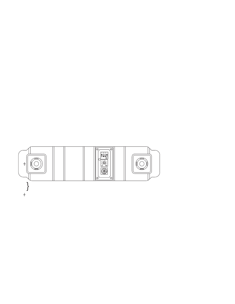
Wiring Connections
The SVT is used in conjunction with an external pressure switch
or relay for on-demand cleaning or down-time cleaning. A simple
on-off system can be established with a single pressure switch
connected to pin 3-4. A Dwyer
®
Photohelic
®
high and low limit
switch gage can be used to achieve better control. These
switches must be isolated contact. The common must not be
connected to the equipment contacts or protected ground, since
these may introduce electrical noise and cause improper
operation or possible damage to the control relays. See Figure
1.
Wiring SVT/SVTE (2 DIN Connectors)
1. Remove center screw and pull wiring assembly from
body.
2. Remove gasket and place small screw driver in slot to pry
out the terminal block from the body.
3. Thread wire through the gland nut, gland gasket, washer
and connector cover.
4. Connect wires to proper terminals on the terminal block.
5. Snap terminal block back onto the body. Reinstall the
center screw and screw back into the SVT/SVTE body.
Note: Do not change the power supply DIN (Black) with the
switch input DIN (Gray). The black DIN connector is specially
designed for the power supply, changing DIN connectors can
damage the SVT/SVTE.
Figure 1
POWER SUPPLY
GROUND TERMINAL
CONTROL
AND
TIMER
SETTINGS
PIN 1-2: EXPANSION MODULE
PIN 3-4: SWITCH INPUT
1
4
3
2
L
N
P
O
W
E
R
L
N