Dwyer SCC-FRQ/C User Manual
Model scc-frq/c, Single channel module, Open signal family
Model SCC-FRQ/C
Single Channel Module
NOTE
:
THIS
IS
A
FACTORY
CONFIGURED
UNIT
SCC
OPEN SIGNAL Family
Each SCC-FRQ/C unit is configured and calibrated
at the factory for the input signal range and volt-
age output range printed by the factory on the
SCC unit’s side-label.
The SCC-FRQ/C unit is capable of accommodat-
ing a 0 to 25KHz input frequency at a signal mag-
nitude of up to 250 volts and provides a 0 to
20mA or 4 to 20mA output signal. Unit re-con-
figuration requires Dwyer Instrument’s, Inc. SC
Configurator Utility
This SCC unit may be reconfigured by a user at
any time via their personal computer (PC) or
handheld personal computer (HPC) by installing
Dwyer Instrument’s Windows
®/
PC or Windows
®/
CE HPC
based SC Configurator Utility, interfac-
ing the SCC unit to the computer’s RS-232C
comm port with an SCCConfiguration Cable (sold
separately), and then changing the unit’s input/
output configuration settings.
FACTORY CONFIGURATION
•
15 - 32VDC, 30mA external supply voltage
Mandatory:
Optional:
•
SC Configuration Package (Part No. SCC-
CC-A1) Package consists of: SC
Configurator Utility and SCC Configura-
tion Cable.
REQUIREMENTS
The SCC family of single channel signal condi-
tioning and isolating modues are intelligent, user
programmable, high-accuracy, user friendly, sig-
nal conditioning units.
Each SCC model supports one (1) specific analog
signal-type on its input channel and outputs ei-
ther one (1) high-level current or voltage signal
depending upon model. A diverse SCC model
family permits users to select the model which
meets their unique signal conditioning needs.
OPERATIONAL DESCRIPTION
INSTALLATION
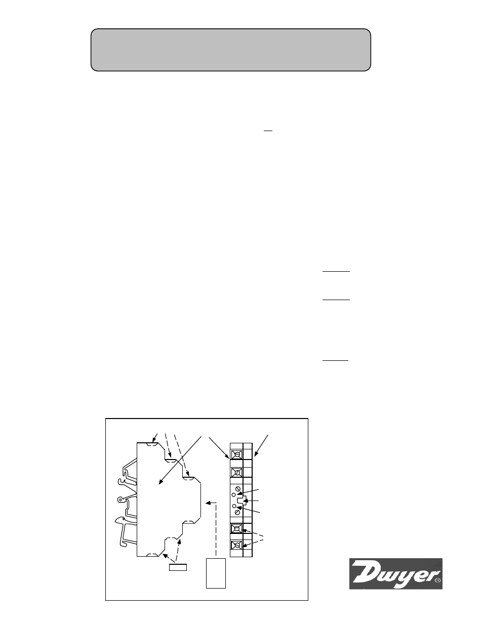
1
4
3
2
6
5
GREEN LED
RED LED
CABLE
PORT
TERMINAL
BLOCK
ENCLOSURE
ENCLOSURE
COVER
SNAP-ON TAB
(COVERS COMM CABLE PORT)
SNAP-ON TAB
(TERMINAL MARKERS)
WIRING
TERMINALS
TERMINAL
SET SCREW
1 . Mount SCC unit on standard TS32 or TS35
DIN rail.
2. See wiring diagram on reverse side. Connect
external 15 to 32VDC power source to SCC
unit:
Positive (+) to SCC terminal +VDC
Negative (-) to SCC terminal -FRQ/-VDC
DIAGNOSTIC TOOLS
Two LEDs one RED and one GREEN are located
on the front face of the SCC’s enclosure and pro-
vide user with visual indication as to unit opera-
tion.
LED FUNCTIONALITY
LED’s have three operational states:
Steady ON
Steady OFF
Blinking
Condition: GREEN = BLINKING
RED = Steady OFF
Meaning:
Module is processing data.
Condition: GREEN = Steady ON
RED = Steady ON
Meaning: 1) Configuration data is not loaded in
module memory. -OR- 2) During module re-con-
figuration both LED’s are normally ON indicat-
ing data is being properly transferred to or from
module memory.
Condition: GREEN = BLINKING
RED = BLINKING
Meaning: The measured input signal is outside
the modules configured range. When the signal is
within configured range the LED’s indicate nor-
mal operation.
All other combinations indicate the module is not
operating correctly.
SCC models may be purchased with a factory pre-
set configuration for plug-n-play application or
available unconfigured so user may configure the
unit to meet their unique need. All SCC models
may be configured/reconfigured by a user at any-
time through use of an optional SC Configuration
Package.
Theory of Operation - An analog world input signal
arriving at the MCC unit is isolated, filtered, am-
plified, scaled and/or linearized (as required) by the
units onboard microprocessor under the direction
of the unit’s configuration parameters set by the
user (or factory) via Windows
®
/PC or Windows
®
/
CE HPC (Handheld Personal Computer) based SC
Configurator Utility.
The conditioned signal is then converted to a high
level analog current or voltage output signal (de-
pending upon model) and presented at the unit’s
isolated output.
3 . Connect input frequency device to SCC unit:
Positive (+) to SCC terminal +FRQ
Negative (-) to SCC terminal -FRQ/-VDC
4 . Connect output actuator/device to SCC unit:
Positive (+) to SCC terminal +I OUT
Negative (-) to SCC terminal -OUT