Input programming, Range selection chart, Popular input range setups – Dwyer SCL1090 User Manual
Page 3: Input
949-0529
Rev. 2
Page 3 of 8 December,
2004
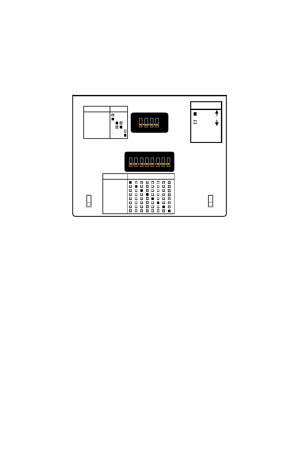
INPUT PROGRAMMING
Use the following chart to select the input type and range for your process.
Turn on the appropriate switch(s) (as indicated) on SW1 for the input and
SW4 for the range desired.
RANGE SELECTION CHART
KEY
= ON
= OFF
BLANK =
NOT
APPLICABLE
SW1
290-2887
SW4
VOLTAGE
CURRENT
UNIPOLAR
BIPOLAR
ZERO BASED
ZERO +20%
MODE
1 2 3 4
INPUT
1 2 3 4 5 6 7 8
1 2 3 4 5 6 7 8
ON
1 2 3 4
ON
1 2 3 4 5 6 7 8
ON
10mV/1mA
50mV/5mA
100mV/10mA
200mV/20mA
0.5V/50mA
1V/100mA
5V
10V
RANGE
POPULAR INPUT RANGE SETUPS
For all of the settings below, all switches are assumed to be off unless
noted.
4 to 20 mA:
On switch SW-1 turn on switches 1, 2, and 4. On switch SW-4 turn on
switch 4.
10 to 50 mA:
On switch SW-1 turn on switches 1, 2, and 4. On switch SW-4 turn on
switch 5.
0 to 20 mA:
On switch SW-1 turn on switches 1 and 2. On switch SW-4 turn on switch
4.
0 to 10 V:
On switch SW-1 turn on switch 2. On switch SW-4 turn on switch 8.
-10 to +10 mV:
On switch SW-1 turn on switch 3. On switch SW-4 turn on switch 1.