Output programming, Function chart – Dwyer SC1290 User Manual
Page 4
949-0530
Rev. 2
Page 4 of 8 December,
2004
Using the Figure 4 (next page), set up the switches on SW2 for
Alarm A and Alarm B.
For dual alarm relays triggered by
Alarm A, set switch 5 to DUAL
. When switch 5 is set to
DUAL
(
on
), switches 6 and 7 have no effect.
OUTPUT PROGRAMMING
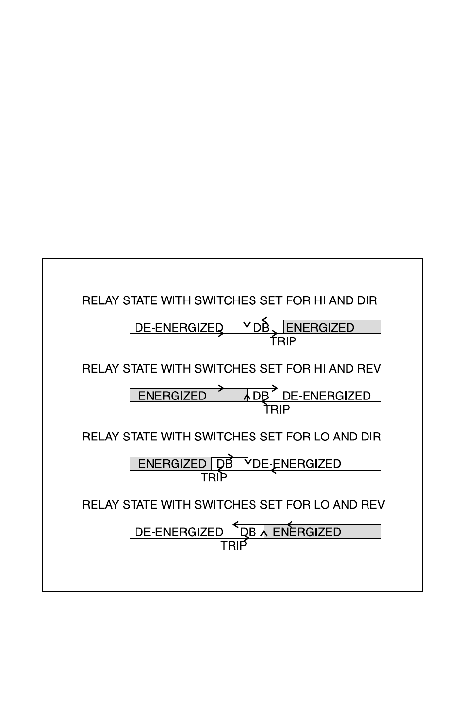
Since the alarms can be set for reverse or direct action, high or low
function, and has normally open and normally closed contacts; the
number of combinations of actual output behavior is quite large.
First, decide how you want the outputs to behave. Will the relay
energize or de-energize at the trip point? Will the relay trip on an
increasing or decreasing signal? Is the dead band above or below
the trip point?
It is impor tant to answer these questions before setting up the mod-
ule. The following Function Char t illustrates the most likely combi-
nations of settings.
Function Chart
Figure 3
- DPL110 (2 pages)
- LLC (2 pages)
- Ultra-Mag™ (2 pages)
- 195 (10 pages)
- F6 (2 pages)
- F7 (2 pages)
- F7-EB (2 pages)
- L4 (4 pages)
- L4 (16 pages)
- L6 (4 pages)
- L6 (16 pages)
- L10 (2 pages)
- L8 (2 pages)
- 221 (4 pages)
- F7-BB (2 pages)
- F7-MLK (2 pages)
- FSW2 (2 pages)
- CFS2 (4 pages)
- PS (4 pages)
- OLS (2 pages)
- PLS (4 pages)
- PLS2 (2 pages)
- LTC (2 pages)
- LTS (1 page)
- TFLS (4 pages)
- TFLS2 (2 pages)
- CTF (2 pages)
- VRLS (2 pages)
- 16L (28 pages)
- TCS (2 pages)
- TS2 (2 pages)
- TSX (2 pages)
- TS (2 pages)
- TSS2 (4 pages)
- TSWB (2 pages)
- TS3 (4 pages)
- TSX3 (4 pages)
- 40T (2 pages)
- TSCC (2 pages)
- DA-7035N (4 pages)
- 862E (1 page)
- DFS (2 pages)
- SC1490 (8 pages)
- TSF (2 pages)