Dwyer instruments, inc – Dwyer WTP-W User Manual
Page 2
Training Output Models
Temperature/Set Point Output Modules
• Attach desired output modules to receiver as described in output
module manual.
• Apply power to the receiver and output modules (LED on receiver
should be lit. LED on output module will flash and go out).
• Remove the lid of sensor and install the batteries (observe polarity).
LED located at the bottom right of the circuit board next to the set
point adjustment knob (if equipped) will flash every 10 seconds.
• Press and hold the plastic service button on the output module to be
programmed. At the same time, press for one second and release the
button on the sensor. When the LED on the output module lights,
release the service button. The LED on the output module will go out
after the button is released.
• Output module LED will flash when it receives data from sensor.
• If equipped, set point adjustment should be programmed to a WM-S
output module using the above steps except you will push the
override button on the sensor instead of the transmitter training button
(on sensors that are not ordered with external override buttons, the
override button is located inside the housing).
• The override button can be programmed in parallel with a previously
trained set point or temperature output module or using a separate
output module. See below section on training override output
modules in parallel or use same steps as training the set point
adjustment when using a separate output module.
• Close cover and mount the transmitter to location within 100 feet of
receiver.
Override Output Module in Parallel to Temperature or Set Point
When override button is trained in parallel to the temperature or set point
output module, that output module will measure its lowest value for 5
seconds when the override button is pressed. Then, it will resume its
normal operation.
• If temperature or set point output module has not been trained, please
train that module before proceeding.
• Remove output module cover by squeezing the top and bottom of the
housing.
• Apply power to the receiver and output module (LED on receiver will
remain lit).
• Remove the cover from the sensor and insert the batteries (observe
polarity). LED located at the bottom right of the circuit board will
flash approximately every 10 seconds.
• On the output module, move the jumper labeled J4 to the training
position (see Figure 4).
• Press and hold the SW1 next to the LED on the output module.
• At the same time press for one second and release the override
button on the sensor. When the LED on the output module lights,
release the service button. The LED on the output module will go out
after the button is released.
• On the output module, move the jumper labeled J4 to the storage
position.
• Replace the cover on the output module.
• Mount the sensor within 100 feet of a repeater or receiver.
©Copyright 2009 Dwyer Instruments, Inc.
Printed in U.S.A. 12/09
FR# R6-443760-00
DWYER INSTRUMENTS, INC.
Phone: 219/879-8000
www.dwyer-inst.com
P.O. BOX 373 • MICHIGAN CITY, INDIANA 46361, U.S.A.
Fax: 219/872-9057 e-mail: [email protected]
MAINTENANCE, CLEANING AND REPAIR
After final installation of the unit, no routine maintenance is required. A
periodic check of the system calibration is recommended. The Series
WTP-W is not field serviceable and should be returned if repair is
needed (field repair should not be attempted and may void warranty). Be
sure to include a brief description of the problem plus any relevant
application notes. Contact customer service to receive a return goods
authorization number before shipping.
Error
Temperature reading is
incorrect
Output module red LED
flashing rapidly
Temperature reading is
coming out of wrong
output module
Required Action(s)
• Check wire from output modules to
controller for proper connections and
polarities.
• Check to see if the controller’s software
is configured correctly.
• Check transmitter to see if its LED
flashes every 10 seconds. If not, change
batteries.
• Check power to the receiver and output
module.
• Check output module LED. If blinking
fast, retrain output module.
• Check transmitter to see if its LED
flashes every 10 seconds. If not, change
batteries.
• Retrain output module.
• Retrain output module.
DIAGNOSTICS
Figure 2: Polarity of Battery Installation
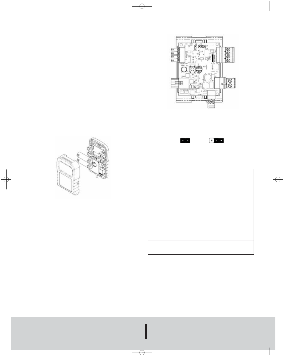
Figure 3: Output Module
Figure 4: J4 Jumper on Output Module
Training Position
Storage Position
W-WTP-W:E-53(english) 12/28/09 10:51 AM Page 2