Dwyer instruments, inc – Dwyer CDW2 User Manual
Page 2
©Copyright 2013 Dwyer Instruments, Inc.
Printed in U.S.A. 3/13
FR# R6-444001-00 Rev. 2
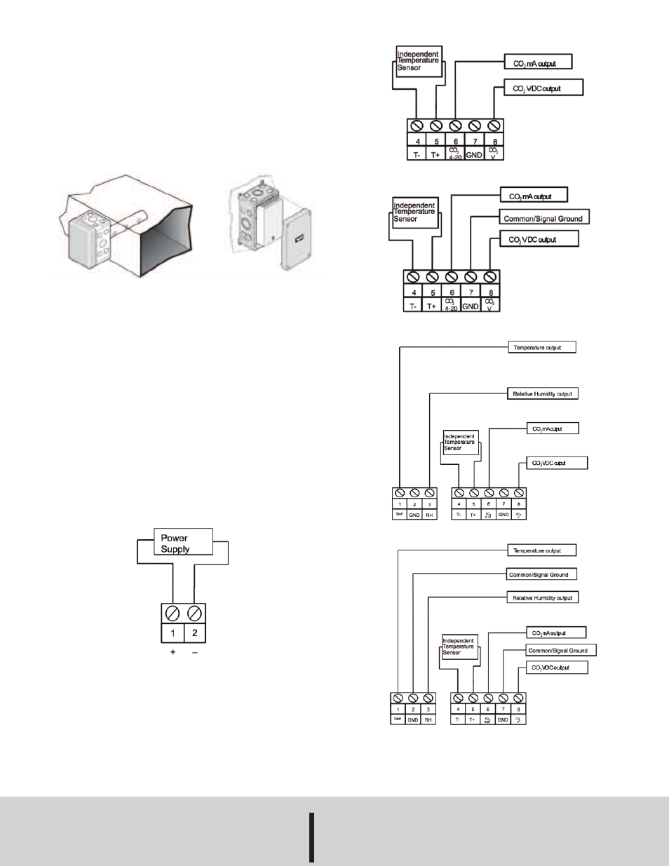
WIRING
The CDW2 series has two basic configurations. The first provides three active outputs
(relative humidity, temperature, CO
2
) and an independent thermistor. The other
configuration provides only the CO
2
outputs and an independent thermistor. The
power requirements and wiring for the two configurations are identical. The
recommended wire gauge is 18 to 22 AWG (1.0 to 0.75 metric).
ACCESSORIES
Model 1508 Duct Mount Enclosure – The CDW2 series can be installed in a model
1508 duct mount enclosure.
Model 1552 Outside Air Enclosure – This NEMA-3R weatherproof enclosure
includes thermostat and allows installation of the sensor in environments with
temperatures down to -40°F (-40°C).
Calibration
The Series CDW2 is factory set with the proprietary logic function activated. The logic
function allows the sensor to continuously recalibrate itself when the indoor
concentrations drop to levels similar to outside air conditions when the building is
unoccupied. The building must be unoccupied for a minimum of 4 hours or more for
this self calibration to be effective. The logic allows the sensor to maintain its
calibration over the life of the sensor. If the building is occupied 24 hours a day or
there is significant sources of CO
2
while the building is unoccupied, the logic function
should be turned off.
MAINTENANCE/REPAIR
Upon final installation of the Series CDW2, no routine maintenance is required. The
Series CDW2 is not field serviceable and should be returned if repair is needed. Field
repair should not be attempted and may void warranty.
WARRANTY/RETURN
Refer to “Terms and Conditions of Sales” in our catalog and on our website. Contact
customer service to receive a Return Goods Authorization number before shipping the
product back for repair. Be sure to include a brief description of the problem plus any
additional application notes.
WIRING DIAGRAMS
Figure 8: Duct mount enclosure (left), outside air enclosure (right)
Figure 3: Power block terminal connection. For use on all models.
(See Power Supply Requirements)
Figure 4: 3-wire configuration for use with models CDW2-2W4XX
Figure 5: 4-wire configuration for use with models CDW2-2W4XX
Figure 6: 3-wire configuration for use with models CDW2-2W4XX-LCD
Figure 7: 4-wire configuration for use with models CDW2-2W4XX-LCD
DWYER INSTRUMENTS, INC.
Phone: 219/879-8000
www.dwyer-inst.com
P.O. BOX 373 • MICHIGAN CITY, INDIANA 46360, U.S.A. Fax: 219/872-9057
e-mail: [email protected]