Dwyer instruments, inc – Dwyer CDD User Manual
Page 2
©Copyright 2012 Dwyer Instruments, Inc.
Printed in U.S.A. 6/12
FR# R6-443629-00 Rev. 3
CALIBRATION
The Series CDD is factory set with the proprietary logic function activat-
ed. The logic function allows the sensor to continuously re-calibrate itself
when the indoor concentrations drop to levels similar to outside air con-
ditions when the building is unoccupied. The building must be unoccu-
pied for a minimum of 4 hours or more for this self-calibration to be
effective. The logic allows the sensor to maintain its calibration over the
life of the sensor. If a building is occupied 24 hours a day or there is sig-
nificant sources of CO
2
while the building is unoccupied, the transmitter
should be ordered with the logic function deactivated.
MAINTENANCE
Upon final installation of the Series CDD Duct Mount Carbon Dioxide
Transmitter, no routine maintenance is required. A periodic check of
system calibration is recommended. The Series CDD is not field
serviceable and should be returned if repair is needed (field repair
should not be attempted and may void warranty). Be sure to include a
brief description of the problem plus any relevant application notes.
Contact customer service to receive a return goods authorization
number before shipping.
DWYER INSTRUMENTS, INC.
Phone: 219/879-8000
www.dwyer-inst.com
P.O. BOX 373 • MICHIGAN CITY, INDIANA 46360, U.S.A.
Fax: 219/872-9057
e-mail: [email protected]
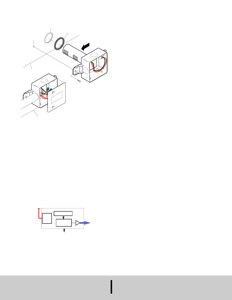
Mounting
AI R
F L
O W
AIR
F L
OW
AIR
FLO
W
Drill /
Punch
1/8˝ Holes
Duct
Conduit
Gasket
(Supplied)
Drill /
Cut
1-1/4˝ Hole
1. Before installing sensor, note the direction of the airflow.
Ensure all mounting holes are sealed tightly.
2. Drill/Cut one 1-1/2˝ hole / Punch/Drill one 1/8˝ hole.
3. Slide sensor into 1-1/2˝ hole and secure with screws.
Wiring Information
Refer to Figure B for wiring information.
Red - Input Power
Brown - Vout
Black - Ground
µController
Power
Supply
Red Wire
Brown Wire
Analog Out
(0 to 10 VDC)
(0 to 2000 PPM)
Common
Black Wire
Sensor Optics
Input Power
18 VDC to 42 VDC or
18 VAC to 30 VAC
RMS
50/60 Hz
Figure A
Figure B