Wiring diagrams, Calibration, Troubleshooting – Dwyer CLT User Manual
Page 2
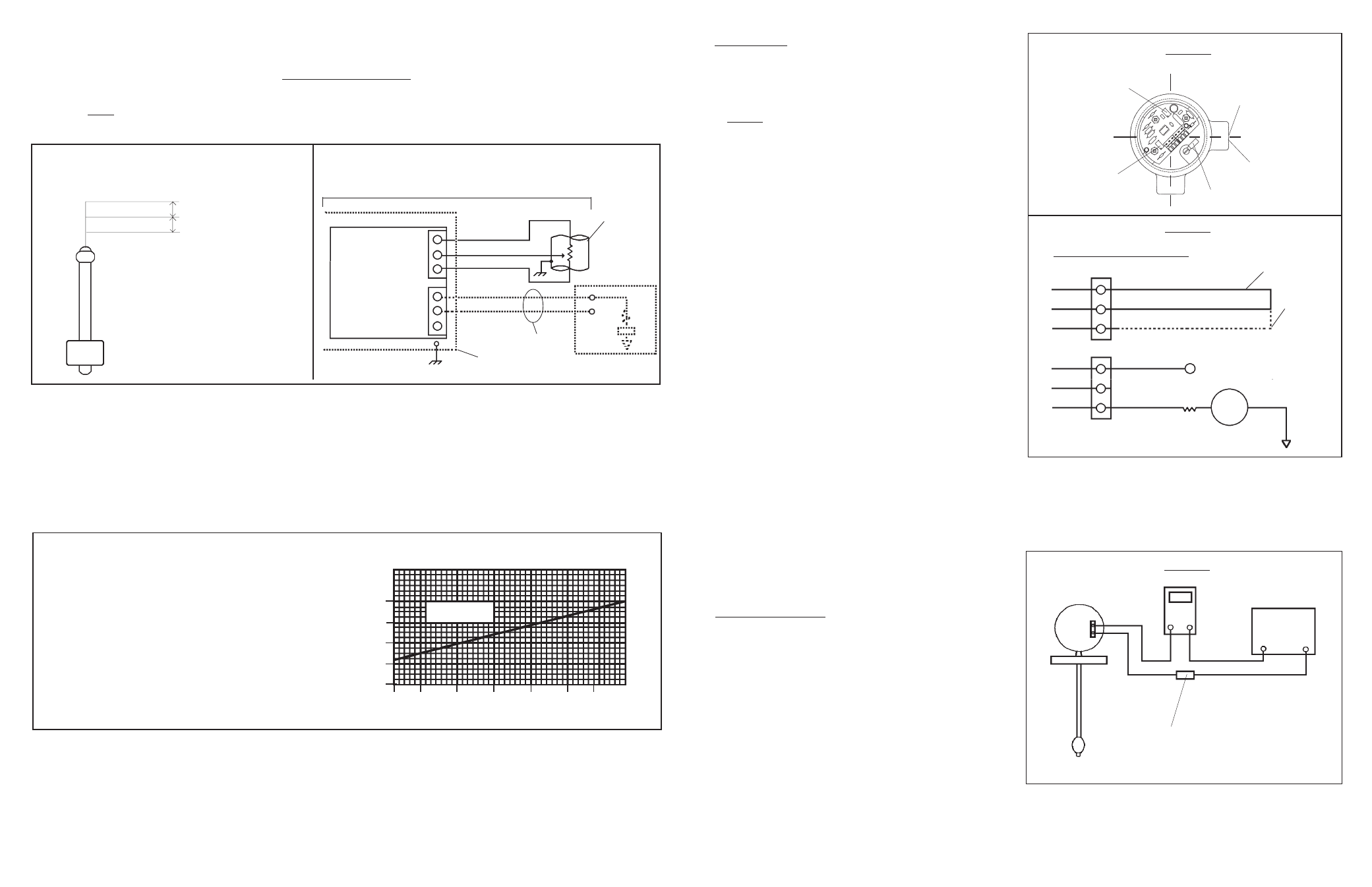
Note: For hazardous area applications, use an appropriate intrinsically safe interface device.
Wiring Diagrams
Calibration should be performed with the probe
disconnected from the signal conditioner. Turn
off power to loop. Disconnect the red, black and
white wires from terminals 1, 2, and 3.
Adjust both the null and span potentiometers at
approximately mid-range. (Figure 1)
Wire as shown per Figure 2, connecting a jumper
wire in place of the black and white probe wires.
Connect an ammeter in series to monitor loop
current. Apply power to loop. Adjust null pot for
4mA.
Remove power from loop. Reposition the jumper
wire in place of red and white probe wires.
Reapply power and with the span pot, set the
output current to 20mA.
Repeat Steps C and D for final adjustment.
If power is maintained during jumper connections,
current level may increase to 36mA. This is
normal. Current will return to regular readings
when connections are made.
Calibration
The signal conditioner on your CLT has been Factory-
set. You do not need to calibrate.
Troubleshooting
Verify proper wiring, power supply, and loop resistance. If
transmitter is not functioning properly, isolate the transmitter
from the system and wire per Figure 3. Meter should read
4mA with float at bottom and 20mA with float on top of
transmitter. If unit is still not operating properly, please
consult Factory for further troubleshooting details.
A.
B.
C.
D.
E.
F.
Steps:
Excitation Required for Transmitters
Using 4-20 mA Signal Conditioners
The minimum excitation required for operation of
transmitters with 4-20 mA, DC signal converters
(See Chart) can be determined for a given total loop
resistance from the graph shown. (Total loop resis-
tance = the sum of the DC termination resistance plus
loop resistance.) For optimum operation, which is a
function of source voltage (+V
A
) and total loop resis-
tance, the source voltage value used should be above
the minimum load line for the related loop resistance.
Area
of Operation
DC Source Voltage
40
30
R
L
(Ohms) Termination Plus DC Loop Resistance
0 200 400 600 800 1000 1200
Minimum Excitation Required For Loop Resistance
20
10
0
Wiring Diagram
Analog Output (Proportional Voltage)
Output: Proportional
Voltage
Wiring Diagram
(4-20mA Output)
Input: 10 - 30 VDC
Red
Black
White
Transmitter
or
Simulator
Junction
Box
4-20 mA Tank Level Transmitter
1
Red
Wht
Blk
Process
Control
Loop
+VA
Voltage
Source
3
2
4
5
6
R
L
1/2" Trade Size
(both Ports)
Span
Potentiometer
Null
Potentiometer
Customer Wiring
(See Wiring Diagram)
Ground Terminal
Figure 1
Figure 2
1
5
Red
White
Black
Brown
Wht/Blk
Orange
Using 300 Ohm Resistor
Place Jumper
Here for 4 mA
Output
Place Jumper
Here for 20 mA
Output
+V (Typically 24V)
Ammeter
R
Loop
+
_
3
2
6
4
Figure 3
+24V
Return
4.12
AMMETER
COM
mA
Power Supply
(24 VDC)
+
_
Choose loop resistance (RL)
to match application