Dwyer 204 User Manual
Page 3
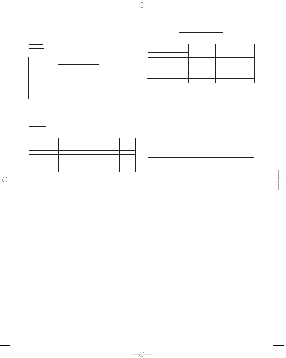
FLANGE AND FLOAT SPECIFICATIONS
Series 221, 223, 224
One vertical and one horizontal 1˝ NPT pipe connection.
Type 221: (1) vertical and (1) horizontal 1˝ NPT pipe connection.
Type 223: (1) flange vertical and (1) flange horizontal 1˝ RF forged
steel.
Type 224: Both flanges vertical 1˝ RF forged steel.
Type
221
223
224
Minimum
Specific
Gravity
0.6
0.75
0.6
0.75
100°F
600 psi
1000 psi
600 psi
600 psi
275 psi
720 psi
1000 psi
475°F Max.
550 psi
850 psi
550 psi
550 psi
150 psi
625 psi
850 psi
Code
C1-60
C1-75
C1-360
C1-660
C1-175
C1-375
C1-675
Pressure Rating At
Flange
Class PSI
---
---
300
600
150
300
600
Type 1271: (1) vertical and (1) horizontal 1˝ socket weld pipe con-
nection.
Type 1273: (1) flange vertical and (1) flange horizontal 1˝ RF forged
steel.
Type 1274: Both flanges vertical 1˝ RF forged steel.
Type
1271
1273
1274
Minimum
Specific
Gravity
0.58
0.58
0.58
0.58
0.58
660°F
2325 psi
1520 psi
2325 psi
1520 psi
2325 psi
Code
C1-58
C1-958
C1-1558
C1-958
C1-1558
Pressure Rating At
Flange
Class PSI
---
900
1500
900
1500
CIRCUIT ARRANGEMENTS
Controls with Mercury Switches
Single Stage Only
120/240 V
-4820
-4821
-4815
-4814
-4813
Specification No.
440 V
-5820
-5821
-5815
-5814
-5813
Circuit
Arrangement
SP-ST
SP-ST
SP-DT
DP-ST
DP-ST
Circuit Response
to Liquid Level
Changes
Closes As Level Falls
Closes As Level Rises
One Circuit Closes As
Other Circuit Opens
Closes As Level Falls
Closes As Level Rises
Two-Stage Operation (With Mercury Switches). Any two circuits shown
in circuit arrangement table are available on each stage for 120/240 volts.
Example: -4820-13 designates a SP-ST lower stage to close as level falls
and a DP-ST upper stage opens as level falls.
Circuit Arrangements
With Snap-Acting Switches
Single Stage
Specification No. -7810 (1) SP-DT Switch
Specification No. -7806 (2) SP-DT Switches
Two Stage
Specification No. -7810-10 SP-DT Each Stage.
Specification No. -7806-06 DP-DT Each Stage.
Do not oil any parts. Never leave cover off the switch operating
mechanism. Do not tamper with switch wires. Position of these
wires is essential to proper operation. Tampering with these wires
will void warranty.
bull O-421C 1/16/03 3:35 PM Page 3