Dwyer 204 User Manual
Page 2
Bulletin O-421C
Page 2
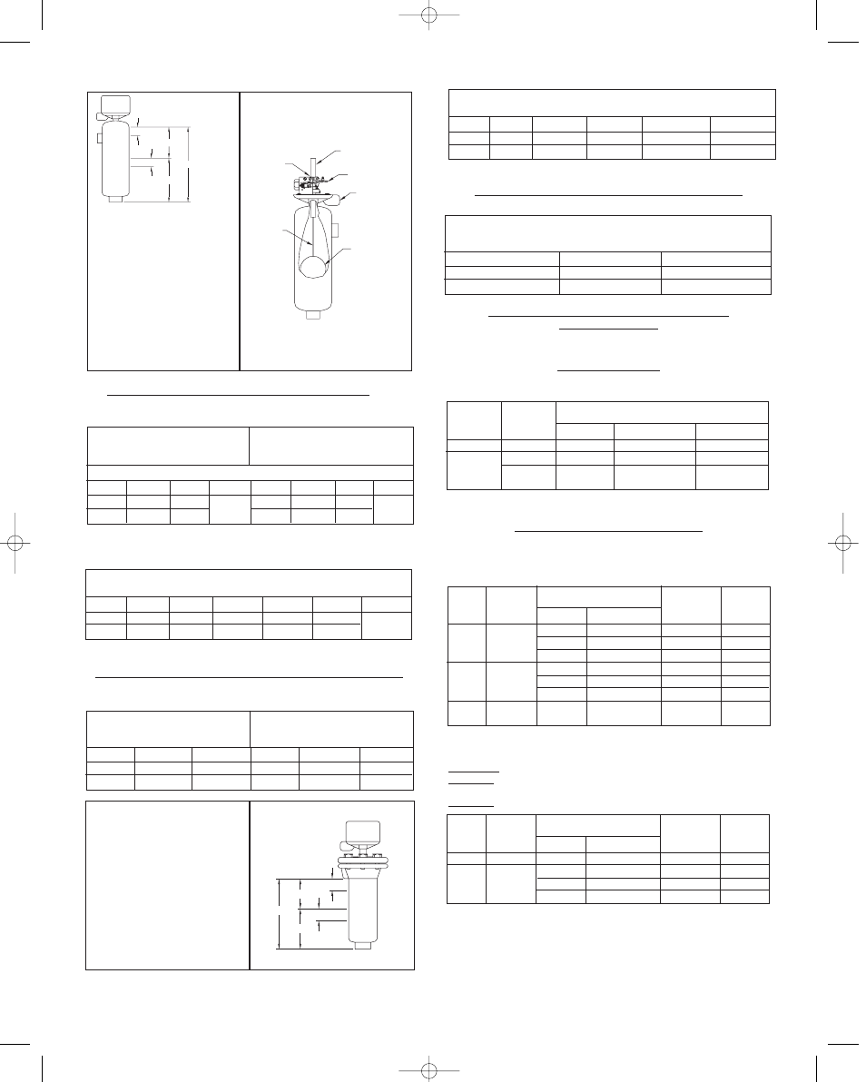
“A” - level at which single (or lower
stage) operates on level rise.
“B” - operating differential single
(or lower stage) - drop in level to
restore switch to original position.
“C” - level at which upper stage
operates on level rise.
“D” - operating differential of upper
stage - drop in level to restore
switch to original position.
“E” - increase in level above “A” to
operate upper stage.
Illustration No. 10
Illustration No. 11
LIQUID LEVEL CHANGES IN INCHES OF WATER FOR-
Series 201, 203, 204, 221, 223, 224, 251, 253, 254
Minimum Specific Gravity 0.75
Single Stage Operation
Specific Gravity 1.0 & .75 -
“A” is Adj. ±1˝
Single Stage with Wide
Differential “A” Not Adjustable
Sp. Gr.
1.0
.75
“A”
7-1/4˝
8˝
“B”
3/4˝
1˝
Code
C1-75
Sp. Gr.
1.0
.75
“A”
8˝
8-3/4˝
“B”
2˝
2˝
Code
C1-75
(See Illustration No. 10)
Two Stage Operation
“A”- Not Adjustable
Sp. Gr.
1.0
.75
“A”
6-1/4˝
7˝
“B”
3/4˝
1˝
“C”
8-1/2˝
9-1/2˝
“D”
1-1/4˝
1-3/4˝
“E”
2-1/4˝
2-1/2˝
Code
C1-75
See Illustration No. 10
LIQUID LEVEL CHANGES IN INCHES FOR SWITCH OPERATION
Series 211, 213, 214, Minimum Specific Gravity 0.6
450 PSI at 100°F, or 300 PSI at 500°F.
Single Stage Operation
“A” is Adj. ±1”
Single Stage with Wide
Differential “A” Not Adjustable
Sp. Gr.
1.0
.6
“A”
6-3/4˝
8˝
“B”
3/4˝
1-1/4˝
Sp. Gr.
1.0
.6
“A”
7-1/2˝
8-3/4˝
“B”
1-3/4˝
2˝
“A” - level at which single (or lower
stage) operates on level rise.
“B” - operating differential single
(or lower stage) - drop in level to
restore switch to original position.
“C” - level at which upper stage
operates on level rise.
“D” - operating differential of upper
stage - drop in level to restore
switch to original position.
“E” - increase in level above “A” to
operate upper stage.
Two Stage Operation
“A”- Not Adjustable
Sp. Gr.
1.0
.6
“A”
5-3/4˝
7˝
“B”
3/4˝
1-1/4˝
“C”
8˝
9-1/2˝
“D”
1-1/4˝
2˝
“E”
2-1/2˝
2-1/4˝
LIQUID LEVEL CHANGES IN INCHES OF WATER FOR -
Series 1271,1273, 1274 - Minimum Specific Gravity 0.58
Single Stage Only
“A” Not Adjustable
Sp. Gr.
1.0
.58
“A”
6-11/16˝
8-1/4˝
“B”
1˝
2˝
FOR SERVICE OTHER THAN SATURATED STEAM
CONSULT FACTORY
Type
201
251
Minimum
Specific
Gravity
0.6
0.75
0.75
100°F
600 psi
1000 psi
1250 psi
and 650°F
750°F Max.
500 psi
750 psi
750 psi
Code
C1-60
C1-75
C1-75
PRESSURE RATINGS
Series 201, 251
One horizontal and one vertical 1˝ NPT pipe connection.
Pressure Rating At
FLANGE AND FLOAT SPECIFICATIONS
Series 203, 253: (1) one vertical and (1) horizontal flanged connec-
tion (1˝ FR forged steel - ANSI specifications.)
Series 204, 254: Two vertical flanged connection (1˝ RF forged
steel - ANSI specifications).
Type
203
204
253
254
Minimum
Specific
Gravity
0.6
0.75
0.75
100°F
275 psi
600 psi
600 psi
275 psi
720 psi
1000 psi
1250 psi
and 650°F
750°F Max.
100 psi
425 psi
500 psi
100 psi
425 psi
750 psi
750 psi
Code
C1-160
C1-360
C1-660
C1-175
C1-375
C1-675
C1-675
Pressure Rating At
Flange
Class PSI
150
300
600
150
300
600
600
Types 211, (1) vertical and (1) horizontal 1˝ NPT pipe connection
Type 213,
(1) flange vertical and (1) flange horizontal 1˝ RF forged
steel.
Type 214,
Both flanges vertical 1˝ RF forged steel.
Type
211
213
214
Minimum
Specific
Gravity
0.6
0.6
100°F
450 psi
275 psi
450 psi
450 psi
500°F Max.
300 psi
150 psi
300 psi
300 psi
Code
C1-60
C1-160
C1-360
C1-660
Pressure Rating At
Flange
Class PSI
---
150
300
600
"D"
"E"
"B"
"A"
"C"
CLAMP SCREW
FLOAT ROD
FLOAT
3/4 NPT COND CONN
ROTATABLE TO 360
°
MERCURY SWITCH
ASSEMBLY
ARMATURE TUBE
"C"
"E"
"B"
"D"
"A"
bull O-421C 1/16/03 3:35 PM Page 2