Dwyer SPPM-C User Manual
Page 2
Wiring
The Series SPPM-C uses a programmable gain amplifier (PGA) to offer the highest
possible resolution on the meter. The 4 to 20 mA input is restricted to the 0 to 2.5
resolution voltage range.
The input voltage range is decided by the software based on the range the user enters
in the scaling section. Software uses the smallest voltage range that accomodates
both voltages entered by user.
Table 1
Figure 2
1 NC Do not connect
2 I+
Positive connection from current loop
3 I-
Negative connection from current loop
4 V+
Positive power supply connection (4 to 30 VDC)
Current Consumption
The current consumption of the panel meter is voltage dependent.
Graph 1
USB Connection
A USB cable is required for customization of the Series SPPM. When connected to a
PC’s USB port, the display is powered by the PC.
Pin Connection
The DIL IDC socket is an alternative to using the screw terminals. This connection can
also be utilized for data busses and alarm outputs. See Figure 3 for the pin layout.
Figure 3
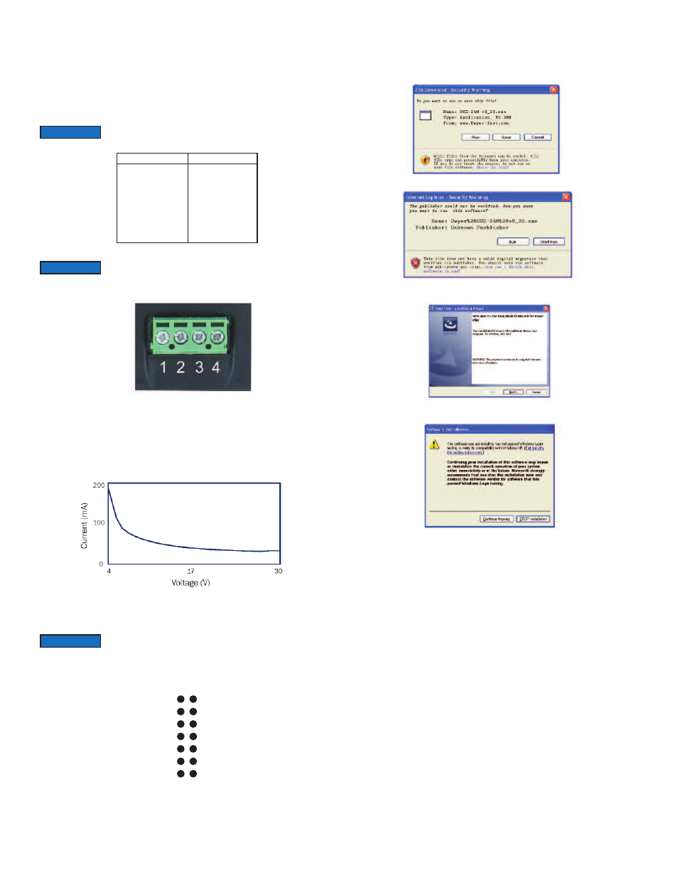
Downloading Software
Customization software is available at www.dwyer-inst.com. To download, follow
these instructions:
1. To begin downloading, click “Run” when prompted.
2. When a security warning appears, click “Run” a second time.
3. As soon as the InstallShield Wizard screen appears, follow the on-screen
instructions.
4. If a Windows
®
logo testing error appears, click “Continue Anyway” .
5. When installation is complete, click “Finish” to quit the installer. The software can
now be used by clicking on the new icon on the desktop.
Launch the software before plugging in the smart panel meter.
DAC1
SPI-SLCK
SPI-MISO
I²C-SCL
ALM1
0V
IN1
0V
SPI-MOSI
SPI-CS2
I²C-SDA
ALM2
V+
IN2
Voltage Range (V)
0 to 1.25
0 to 2.5
0 to 4
0 to 5
0 to 8
0 to 10
0 to 20
0 to 40
Resolution (mV)
0.3
0.6 (4 to 20 mA)
1.0
1.2
2.0
2.4
4.9
9.8
NOTICE
It and I- share a common ground (ie: not floating or isolated from
each other).
NOTICE
The Series SPPM-C requires a fully floating power supply with
respect to the current loop. This supply should be isolated from the
current loop.
NOTICE
0V
DIGI6
DIGI4
DIGI2
ALM2
V+
IN2
DAC1
DIGI5
DIGI3
DIGI1
ALM1
0V
IN1