Dwyer SPPM User Manual
Page 2
Wiring
Series SPPM features two voltage inputs that can be programmed independently.
With the downloadable software, the user can scale the two voltages to create eight
different voltage ranges. The software is programmed to use the smallest range
possible because the smallest voltage range offers the highest resolution. The eight
possible voltage ranges and their corresponding resolutions can be found in the Table
1.
Table 1
Figure 2
IN2 Analog voltage input 2 (maximum of 40 VDC);
IN1 Analog voltage input 1 (maximum of 40 VDC);
0 V 0V power supply input;
V+
Positive power supply input (4 to 30 VDC).
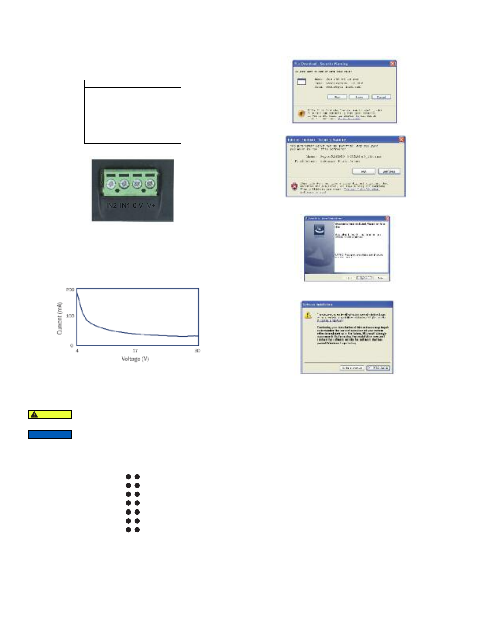
Current Consumption
The current consumption of the panel meter is voltage dependent.
Graph 1
USB Connection
A USB cable is required for customization of the Series SPPM. When connected to a
PC’s USB port, the display is powered by the PC.
Pin Connection
The DIL IDC socket is an alternative to using the screw terminals. This connection can
also be utilized for data busses and alarm outputs. See Figure 3 for the pin layout.
Figure 3
Downloading Software
Customization software is available at www.dwyer-inst.com. To download, follow
these instructions:
1. To begin downloading, click “Run” when prompted.
2. When a security warning appears, click “Run” a second time.
3. As soon as the InstallShield Wizard screen appears, follow the on-screen
instructions.
4. If a Windows
®
logo testing error appears, click “Continue Anyway” .
5. When installation is complete, click “Finish” to quit the installer. The software can
now be used by clicking on the new icon on the desktop.
Launch the software before plugging in the smart panel meter.
DAC1
SPI-SLCK
SPI-MISO
I²C-SCL
ALM1
0V
IN1
0V
SPI-MOSI
SPI-CS2
I²C-SDA
ALM2
V+
IN2
Voltage Range (V)
0 to 1.25
0 to 2.5
0 to 4
0 to 5
0 to 8
0 to 10
0 to 20
0 to 40
Resolution (mV)
0.3
0.6
1.0
1.2
2.0
2.4
4.9
9.8
NOTICE
For safety reasons, the meter should be isolated from both the
supply and signal voltages before connecting the USB.
CAUTION