Dwyer instruments, inc – Dwyer DPT User Manual
Page 4
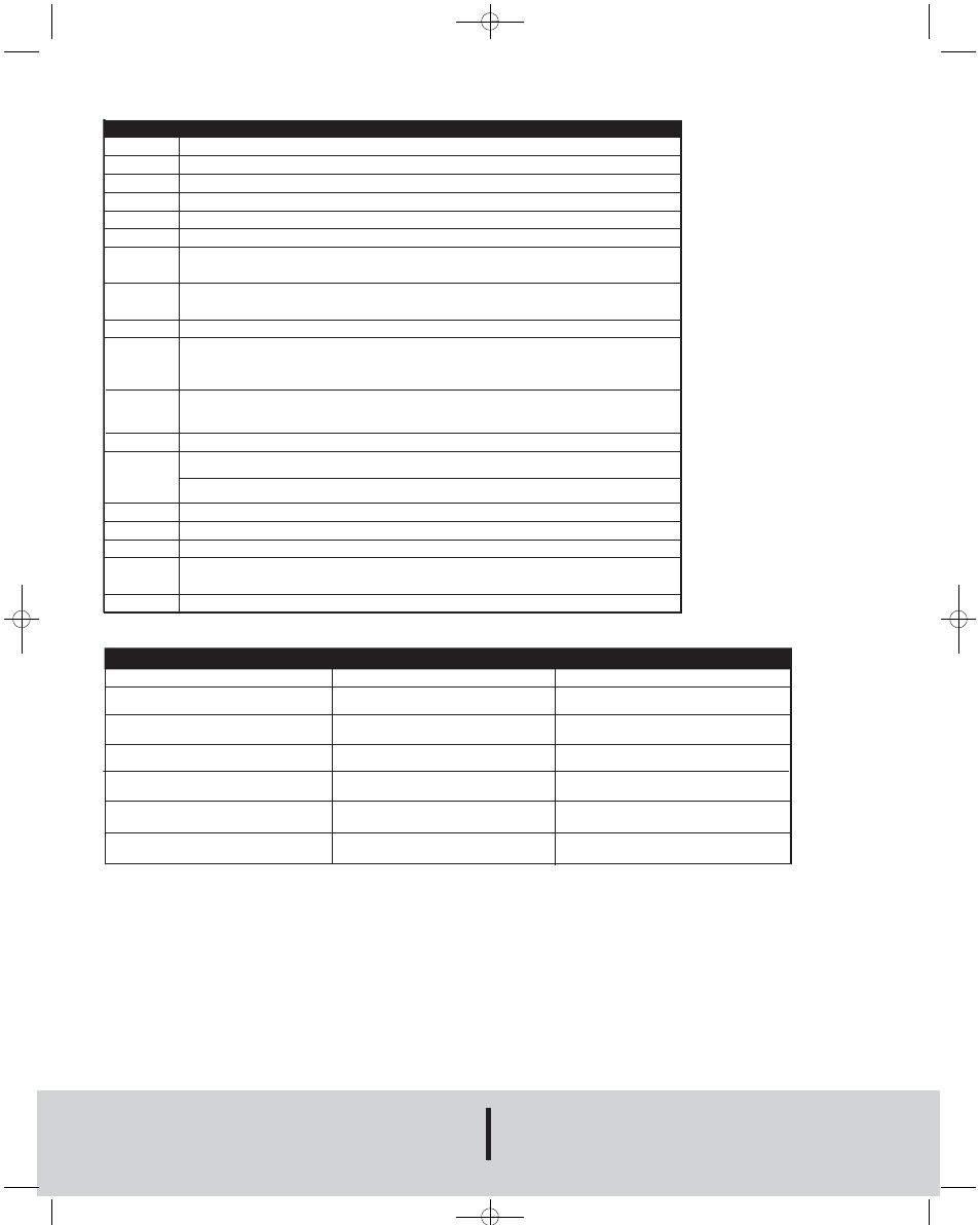
PARAMETERS
TROUBLESHOOTING
WARRANTY
Upon final installation, no routine maintenance is required. A periodic check of the
calibration is recommended. The series DPT is not field serviceable and should be
returned if repair is needed (field repair should not be attempted and may void
warranty). Be sure to include a brief description of the problem plus any relevant
application notes. Contact customer service to receive a returns goods authorization
number before shipping.
Failure
Possible cause
Procedure
No output signal
Cable break
Check connections and cable
No output signal
No/incorrect voltage supply
Adjust the voltage supply to correspond
with the Operating Instructions
No/False output signal
Incorrectly wired
Follow pin assignment (see Instrument
Label / Operating Instructions)
Output signal unchanged after change in pressure
Mechanical overload through over pressure
Replace instrument; if failure reoccurs,
consult the manufacturer
Abnormal zero point signal
Overload limits exceeded
Ensure permissible overload limits are
observed (see Operating Instructions)
Signal span too small
Mechanical overload through over pressure
Replace instrument; if failure reoccurs,
consult the manufacturer
Signal span too small
Power supply too high/too low
Correct the power supply in line with
the Operating Instructions
DWYER INSTRUMENTS, INC.
Phone: 219/879-8000
www.dwyer-inst.com
P.O. BOX 373 • MICHIGAN CITY, INDIANA 46361, U.S.A.
Fax: 219/872-9057
e-mail: [email protected]
©Copyright 2010 Dwyer Instruments, Inc.
Printed in U.S.A. 10/10
FR# RA-443873-00 Rev. 1
Parameter
Description
SP1 / SP2
Hysteresis function: Switch point switch output (1 or 2)
FH1 / FH2
Window function: Window high switch output (1 or 2)
RP1 / RP2
Hysteresis function: Reset point switch output (1 or 2)
FL1 / FL2
Window function: Window low switch output (1 or 2)
EF
Enhanced Programming Functions
RES
Return the set parameter to the Factory Settings
DS1
Switch Delay Time, which must occur without interruption before any electrical signal change occurs
(SP1 or SP2)
DS2
DR1
Switch Delay Time, which must occur without interruption before any electrical signal change occurs
(RP1 or RP2)
DR2
OU1
Switching Function Switching Output (1 or 2)
OU2
HNO = Hysteresis Function, normally open
HNC = Hysteresis Function, normally closed
FNO = Window Function, normally open
FNC = Window Function, normally closed
UNIT
Changing Units
(If the pressure range is higher than the display range, no change of the unit is posssible
and the parameter UNIT is not shown)
0SET
Zero Point adjustment (+ 3% of Nominal Pressure)
DISM
Display value in Display Mode
ACT = Current System Pressure, LOW, HIGH = Minimum, Maximum System Pressure, OFF = Display off;
SP1/FH1 = Function switch point 1, RP1/FL1 = Function reset point1,
SP2/FH2 = Function switch point 2, RP2/FL2 = Function reset point 2
DISU
Display-Update 1, 2, 5, 10 Updates/Second
DISR
Display rotate 180°
RHL
Clear the Min- and Max-value memory
PAS
Password input, 0000 = no password
Password input Digit by Digit
TAG
Input of a 16-digit alphanumeric Measuring Point number
11609185.01
10/2010
P-DPT:TEMPLATE 10/18/10 1:58 PM Page 4