0 calibration, 0 maintenance/repair, 0 electrical installation – Dwyer 682 User Manual
Page 2: 0 series 682 performance specifications
2
3
4.0 CALIBRATION
Every Series 682 is factory calibrated and should require no field adjustment
Whenever possible, any zero and/or span offsets should be corrected by software
adjustments in the user’s control system. However, both zero and span adjustments
are accessible by removing the pan head screws and turning the zero and span
potentiometer screw inside. Use zero and span adjustments on the 682 only if
absolutely necessary. Pan head screws should be replaced after adjustment to
maintain enclosure rating.
Current output units (4-20 mA) are factory calibrated with a 24 VDC loop supply
voltage and a 250 ohm load. The zero factory setting is
±
0.08 mA. The span (full
scale) factory setting is
±
0.16 mA. Zero and span adjustments are approximately
±
1.0 mA.
5.0 MAINTENANCE/REPAIR
After final installation of the Series 682 pressure transducer no routine maintenance
is required. A periodic check of system calibration is recommended. These devices are
not field repairable and should be returned to the factory if recalibration or other
service is required. After first obtaining a Return Goods Authorization (RGA) number,
send the material, freight prepaid, to the following address. Please include a clear
description of the problem plus any application information available.
Dwyer Instruments
Attn: Repair Department
102 Indiana Highway 212
Michigan City, IN 46360
3.0 ELECTRICAL INSTALLATION
The Series 682 is available with the following electrical termination:
2 foot Cable
3.1 Series 682
Series 682 Current Unit
The Series 682 (current output) transducers are true 2-wire, 4-20 mA current output
devices and deliver rated current into any external load of 0-800 ohms. The 682 has a
2-wire cable where red is positive and black is negative. On the Hirschmann
Connector, Pin 1 is positive; Pin 2 is negative and Pin 4 is Ground/Shield.
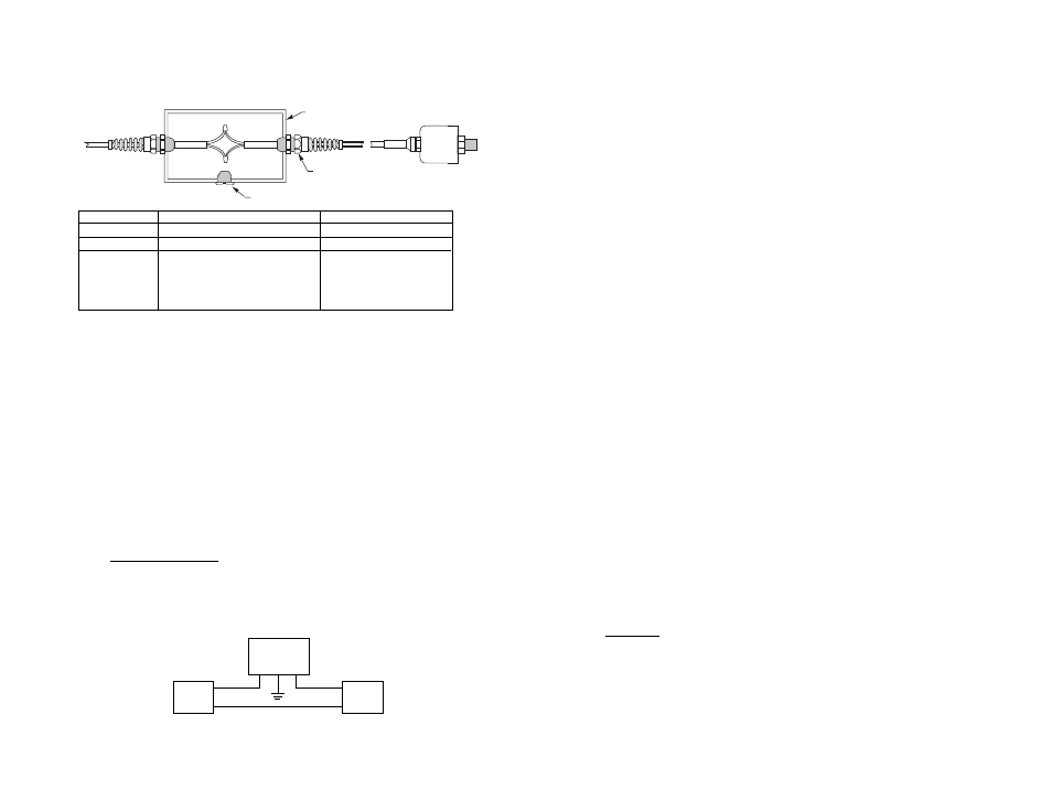
Junction Box Suggestion - The following junction box configuration is a
recommended method of terminating the 682 signal cable in order to achieve
a moisture resistant and vented connection.
Termination:
Junction Box
Cable Strain Relief
Part No.
Q1388PCE
3237 Heyco Flex Fitting
Dimensions:
4.92” x 2.95” x 2.95”
2.50” Long
Manufacturer:
Hoffman Engineering Co.
Heyco
900 Ehlen Drive
Kenilworth, NJ 07033
Anoka, MN 55303
(201) 245-0033
(612) 421-2240
(800) 526-4182
1. Drill one 1/2” dia. hole at each end of junction box for cable strain reliefs.
Note: If conduit is to be installed, omit one 1/2” hole and drill appropriate
hole for conduit.
2. Drill and tap one 1/2” - 13 NC hole in bottom of junction box and install
loosely one 1/2” - 13 NC plastic or stainless steel screw. The clearance
between threads serves as a vent for the box.
3. Install cable strain reliefs in 1/2” dia. holes. If using conduit at one end, be
sure it is sealed properly against moisture.
4. Mount junction box and install cables.
5. A desiccant pack can be placed in the junction box for additional protection.
Series 682
Transducer (4-20
mA)
Power
Supply
Load
(Monitor)
+
+
+
_
_
_
The 4-20 mA current output unit is designed to have current flow in one direction only -
PLEASE OBSERVE POLARITY. We suggest that the electrical cable shield be connected to
the system’s loop circuit ground to improve electrical noise rejection.
Vent Screw
Plastic Junction Box
Strain Relief
206/C206
6.0 SERIES 682 PERFORMANCE SPECIFICATIONS
Accuracy RSS
*
±
0.13% FS
(at constant temperature)
Non-Linearity, BFSL
±
0.1% FS
Hysteresis
0.08% FS
Non-Repeatability
0.02% FS
*RSS of Non-Linearity, Non-Repeatability and Hysteresis.
Thermal Effects
Compensated Range
°
F(
°
C)
-4 to +176 (-20 to +80)
Zero Shift %FS/
°
F(
°
C)
±
1.0 (
±
0.9)
Span Shift %FS/
°
F(
°
C)
±
1.5 (
±
1.4)
Stability
0.5% FS/YR