Dwyer 7314D User Manual
Dwyer instruments, inc, Never put stress on housing, Bulletin a-33-b
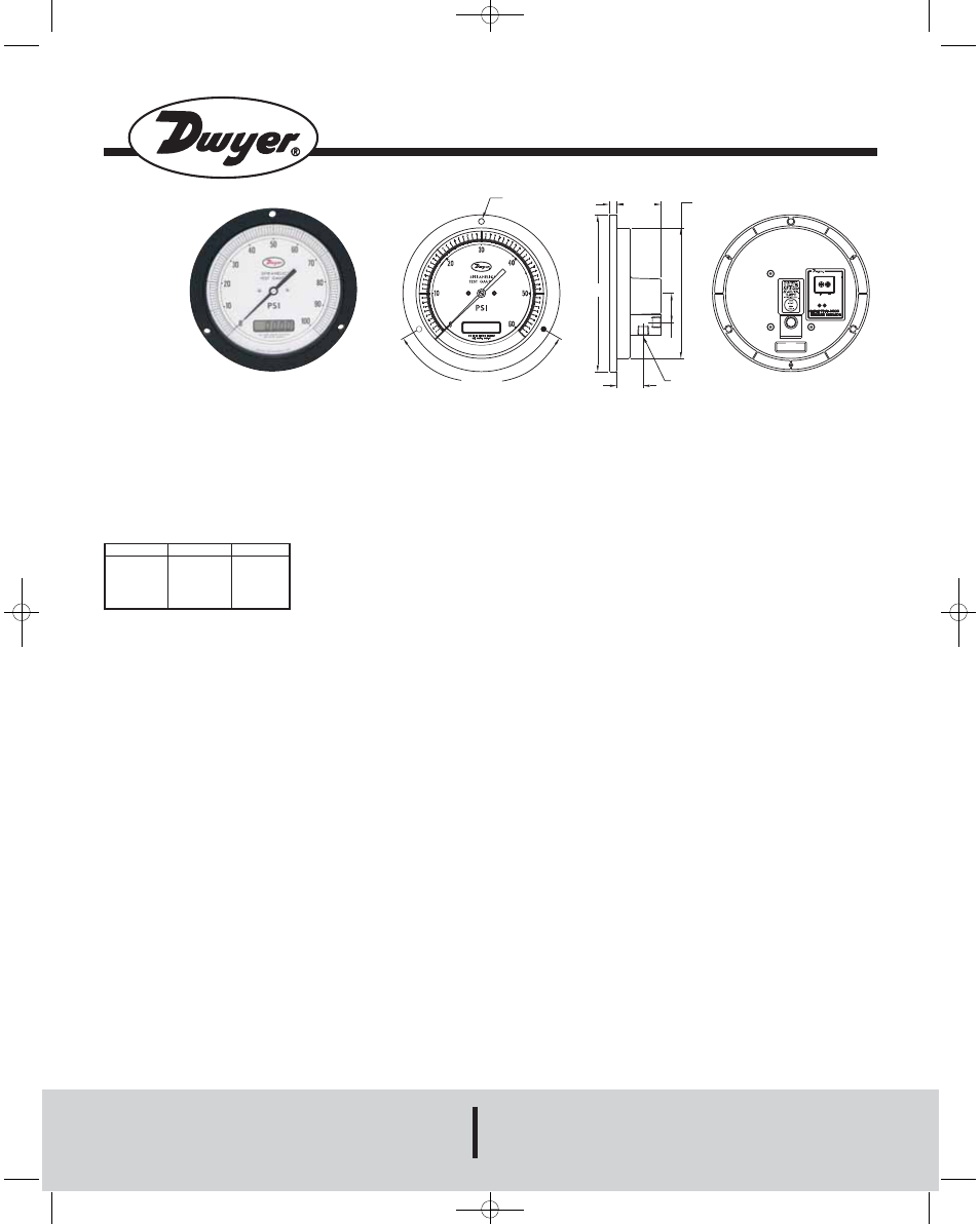
SERIES 7214D & 7314D
SPIRAHELIC
®
PRESSURE GAGE WITH DIGITAL DISPLAY
Specifications - Installation and Operating Instructions
Bulletin A-33-B
B
11/32
[8.732]
2-9/64
[54.37]
1-13/32
[35.71]
1/4 NPT TYP 2 PLACES
1-9/32
[32.54]
C
A
120° TYP.
CAUTION
ALWAYS USE WRENCH ON PRESSURE
BLOCK WHEN TIGHTENING FITTINGS
ZERO
SPAN
NEVER PUT STRESS ON HOUSING
DWYER INSTRUMENTS, INC.
MICHIGAN CITY, IN 46360, U.S.A.
Inconel
®
is a registered trademark of Huntington Alloy Corporation
DWYER INSTRUMENTS, INC.
Phone: 219/879-8000
www.dwyer-inst.com
P.O. BOX 373 • MICHIGAN CITY, INDIANA 46361, U.S.A.
Fax: 219/872-9057
e-mail: [email protected]
Series 7214D & 7314D Models and Ranges
Model
7214D-G100
7214D-G200
7214D-G300
7214D-G600
Model
7314D-G100
7314D-G200
7314D-G300
7314D-G600
Range, PSI
0-100
0-200
0-300
0-600
SPECIFICATIONS
Size: 6˝ (7214D), 8.5˝ (7314D). Size conforms to ASME B40.1.
Accuracy: ASME Grade 3A (1/4% of full scale).
Pressure Connections: 1/4˝ NPT female, duplicated back and bottom.
ASME Specifications: Conforms to ASME B40.1.
Housing: Impact resistant mineral filled nylon.
Position: Calibrated for mounting with scale in vertical position.
Wetted Parts: Inconel
®
Alloy X-750 Bourdon tube, 316 SS connection block.
Movement: Direct drive of pointer.
Temperature Limits: 20 to 120°F (-6.7 to 48.9°C).
Overpressure: 150% of full scale. Recommended operation should be between
25 and 75% of full scale.
Finish: Black.
Weight: 7214D-21 oz. (595 grams) 7314D-1 lb, 11 oz. (765 grams) .
Accessory: (1) 1/4˝ NPT pipe plug.
Electrical
Power Supply: 10-35 VDC; 16-26 VAC.
Warm-Up Time: 10 minutes.
Current Consumption: DC: 38 mA max.; AC: 76 mA max.
Series 7214D & 7314D Dwyer
®
Spirahelic
®
Gages employ a unique triple-wound
helical/spiral Bourdon tube, formed from Inconel
®
Alloy X-750 material for excep-
tionally wide media compatibility and reliability. Units provide ASME Grade 3A
accuracy (1/4%), readable on both a large 6˝ (7214D), 8.5˝ (7314D) analog dial
and a 4-1/2 digit liquid crystal display. A 316 SS connection block includes dual 1/4˝
NPT female ports for a choice of vertical or horizontal piping. Block includes an
integral filter plug to prevent dirt or other foreign material from entering the gage.
Gage fits standard ASME 9.0˝ (229mm) panel cut out.
Installation
1. Select a location free from excess vibration where the temperature limits of 20
to 120°F (-6.7 to 48.9°C) will not be exceeded. Mounting surface should be verti-
cal to match the position in which all standard gages are calibrated. Avoid locations
in direct sunlight which can cause accelerated discoloration of the clear acrylic
lens or where exposure to oil mist or other airborne vapors could likewise result in
lens damage. Make sure the case relief area on the rear is not obstructed. This
hole is designed to direct pressure rearward in the event of a Bourdon tube failure.
See complete safety recommendations on the back of this sheet.
2. Make a panel cutout of 6.5˝ (165.1mm) for Series 7214D gages. Make a panel
cutout of 9˝ (229mm) for Series 7314D gages. See drawing above for bolt circle
diameters and bolt hole sizes.
3. Two 1/4˝ NPT female pressure connections are provided allowing a choice of
vertical (below gage) or horizontal piping. Plug unused port. Use minimal amount
of thread sealant. Too much could block the internal pressure passage.
Caution: When installing fittings or pipe, always use a second wrench on the 1˝
connection block. Do Not allow torque to be transmitted from the block to the gage
case.
Electrical Connections
Caution: Do not exceed specified supply voltage ratings.
Permanent damage not covered by warranty will result.
This unit is not designed for 120 or 240 VAC line operation.
Electrical connections to the Series 7214D & 7314D Spirahelic
®
Pressure gage
with digital display are made to the electrical terminal strip on the rear of the case.
See drawing above. It is not necessary to observe polarity when making electrical
connections. Do observe the maximum VDC and VAC limits listed at left.
Calibration Test
To check calibration, use a dead weight tester or certified test gage with accuracy
of 0.1% or better for ASME Grade 3A gages. The test gage range should be com-
parable to the range of the Dwyer
®
Spirahelic
®
gage being tested. Connect lines
from the two instruments to a tee and a third line from the tee to a controllable
source of pressure. Apply pressure slowly so pressure can equalize throughout the
system. Compare readings. If gage being tested is found to need calibration,
return it freight prepaid to the address below.
Maintenance
No lubrication or periodic servicing is required. Keep case exterior and lens clean.
Use only cleaners compatible with acrylic plastic.
Repairs
Field repair is not recommended and can void warranty. Gages needing calibration
or other service should be returned freight prepaid to:
Dwyer Instruments, Inc.
Attn: Repair Department
102 Indiana Highway 212
Michigan City, IN 46360
A-33-B :7314D IOM 3/1/11 8:41 AM Page 1