Dwyer 7000 User Manual
Page 2
CAUTION: When installing fittings or pipe always us a second wrench on
the 1˝ pressure block DO NOT allow torque to be transmitted from block
to the gage case.
PNEUMATIC CALIBRATION TESTER
Use a dead weight tester or certified test gage with .125% or better accu-
racy. The test gage range should be comparable to the range of the
Spirahelic
®
Pressure Indicating Transmitter being checked. Connect the
lines from the two instruments to a tee and the third line from the tee to
a controllable source of pressure. Apply pressure slowly so pressure
equalizes throughout the system. Compare readings, if gage being test-
ed is found to need calibration, return it, freight prepaid to the factory.
ELECTRICAL CONNECTIONS
CAUTION: Do not exceed specified supply voltage ratings. Permanent
damage not covered by warranty will result. This unit is not designed for
120 or 240 volt AC line operation.
Electrical connections to the Series 7000 Spirahelic
®
Pressure Indicating
Transmitter are made at the rear of the pressure gage. Feed stripped and
tinned leads to the terminal block screws shown below, refer to Figure A
for locations of the terminal block, span and zero adjustments.
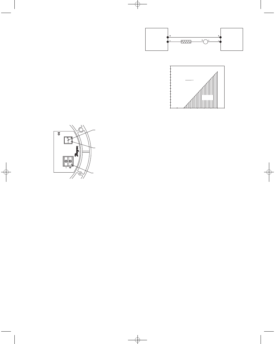
2-Wire Operation - A external power supply delivering 10-35 VDC with
minimum current capability of 40 mA DC (per transmitter), must be used
to power the control loop. See Figure B for connection of the power sup-
ply, transmitter, and receiver. The range of the appropriate receiver load
resistance (R
L
) for the DC power supply voltage available is expressed
by the formula and graph in Figure C. Shielded two wire cable is recom-
mended for control loop wiring. if grounding is required use negative side
of control loop after receiver see Figure B.
PRESSURE RANGING
Each standard Series 7000 Spirahelic
®
Pressure Indicating Transmitter is
factory calibrated to produce a 4 mA output signal at zero pressure and
a 20 mA signal at full scale. Use the following procedure to check or
adjust the output signal calibration.
1. With the unit connected to its companion receiver and power supply,
an accurate milliammeter should be inserted in series with the current
loop. A controllable pressure source capable of achieving the necessary
full scale pressure should be connected to the pressure port of the trans-
mitter and teed to an accurate pressure gage or manometer. The instru-
ment should be calibrated in the same position in which it will be used.
Vertical mounting is recommended.
2. Apply electrical power to the system and allow it to stabilize for 10 min-
utes.
3. With no pressure applied to the transmitter, adjust “Zero” control so
that loop current is 4 mA.
4. Apply full scale pressure and adjust “Span” control so that loop current
is 20 mA.
5. Relieve pressure and allow transmitter to stabilize to 2 minutes.
6. Zero and Span controls are slightly interactive so repeat steps 3
through 5 until zero and full scale pressures consistently produce loop
currents of 4 and 20 mA respectively.
7. Remove milliammeter from the current loop and proceed with final
installation of the transmitter and receiver.
MAXIMUM VALUE (1300 OHMS)
1400
1300
1200
1100
1000
900
800
700
600
500
400
300
200
100
50
0
5
10
15
20
25
30
35
40
OPERATING
REGION
RECEIVER RESIST
ANCE (OHMS)
R L MAX =
Vps-10.0
20mA DC
7000 SERIES
INDICATING
PRESSURE
TRANSMITTER
POWER
SUPPLY
10-35 VDC
mA
RECEIVER
SPAN ADJUST
ZERO ADJUST
TERMINAL BLOCK
SPIRAHELIC INDICA
TING TRANSMITTER
M
O
D
E
L:
RANGE:
SP
AN
ZERO
7000
Fig. A
Fig. B
Fig. C
A-33-A:A-33-A 3/1/11 8:24 AM Page 2