Dwyer instruments, inc – Dwyer 607D User Manual
Page 2
ELECTRICAL CONNECTIONS
Wire Length
The maximum length of wire connecting transmitter and receiver is a function of wire
size and receiver resistance. Wiring should not contribute more than 10% of the
receiver resistance to total loop resistance. For extremely long runs of wiring (over
1000 feet), choose receivers with lower resistance to minimize size and cost of
connecting leads. Where wiring length is under 100 feet, wire as small as 22 AWG
can be used.
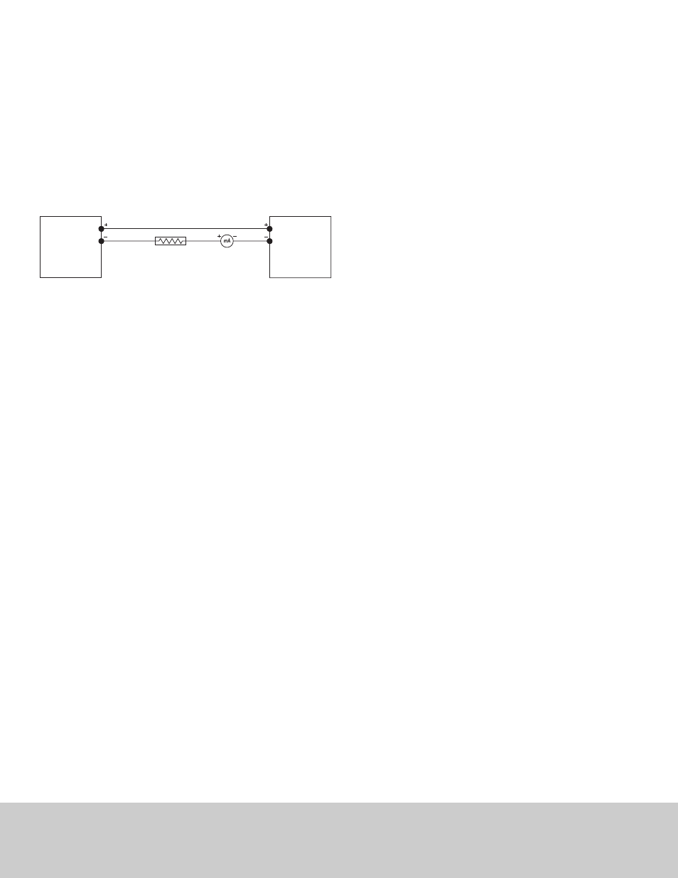
2-Wire Operation
An external power supply delivering 16 to 32 VDC with minimum current capability of
30 mA DC (per transmitter) must be used to power the control loop. Shielded two wire
cable is recommended for control loop wiring. If grounding is required, use the
negative side of the control loop after the receiver. It is not necessary to observe
polarity of control loop connections.
Wiring Diagram
Calibration Check
Each Series 607D Transmitter is factory calibrated to the range given in the model
chart. To check calibration and adjust if necessary, the following procedure should be
used. For purposes of clarification in these instructions, range is defined as that
pressure which, applied to the transmitter, produces 20 milliamps of current in the
loop. Zero pressure is always assumed to be 4 milliamps except on bidirectional
models.
1. With the transmitter connected to the companion receiver, insert an accurate
multimeter in series with the current loop. The multimeter full scale range should
be 30 mA or greater.
2. Connect a controllable pressure source to one leg of a tee with the other two legs
connected to the high pressure port of the transmitter and the third leg to an
accurate test gage or manometer, in an appropriate range. The low pressure port
should be vented to atmosphere. Calibration must be performed with the unit in the
same position in which it will be mounted.
3. Apply electrical power to the unit and allow it to stabilize for 10 minutes.
4. With no pressure applied to the transmitter, adjust ZERO control so that loop
current is 4 mA. Bi-directional zero pressure is 12 mA.
Voltage Output
Series 607D Transmitters can be easily adapted for receivers requiring 1 to 5 or 2 to
10 VDC inputs. Insert a 249 ohm, (1 to 5 VDC) or 499 ohm (2 to 10 VDC) resistor of
the proper power rating in series with the current loop but in parallel with the receiver
input. Locate this resistor as close as possible to the input. Because resistor accuracy
directly influences output signal accuracy, we recommend use of a precision ±0.1%
tolerance resistor to minimize this effect.
MAINTENANCE
Upon final installation of the Series 607D Transmitter, no routine maintenance is
required. The Series 607D is not field serviceable and should be returned if repair is
needed (field repair should not be attempted and may void warranty). Be sure to
include a brief description of the problem plus any relevant application notes. Contact
customer service to receive a return goods authorization number before shipping.
DWYER INSTRUMENTS, INC.
Phone: 219/879-8000
www.dwyer-inst.com
P.O. BOX 373 • MICHIGAN CITY, INDIANA 46360, U.S.A.
Fax: 219/872-9057
e-mail: [email protected]
©Copyright 2012 Dwyer Instruments, Inc.
Printed in U.S.A. 3/12
FR# R1-443884-00 Rev. 2
POWER
SUPPLY
16-32 VDC
PRESSURE
TRANSMITTER
RECEIVER