Dwyer instruments, inc – Dwyer 655A User Manual
Page 2
©Copyright 2009 Dwyer Instruments, Inc.
Printed in U.S.A. 2/09
FR# R1-443718-00
DWYER INSTRUMENTS, INC.
Phone: 219/879-8000
www.dwyer-inst.com
P.O. BOX 373 • MICHIGAN CITY, INDIANA 46361, U.S.A.
Fax: 219/872-9057
e-mail: [email protected]
Electrical Connections
Use A-232 with 6˝ pin connection models
Wire Length
The maximum length of wire connecting the transmitter and receiver is
a function of wire size and receiver resistance. Wiring should not
contribute more than 10% of the receiver resistance to total loop
resistance. For extremely long runs (over 1000 feet (305 m)), choose
receivers with lower resistance to minimize the size and cost of
connecting leads. Where wiring length is under 100 feet (30.5 m), wire
as small as 22 AWG can be used.
MAINTENANCE
Upon final installation of the Series 655A Differential Pressure
Transmitter, no routine maintenance is required. A periodic check of
system calibration is recommended. The Series 655A is not field
serviceable and should be returned if repair is needed (field repair
should not be attempted and may void warranty). Be sure to include a
brief description of the problem plus any relevant application notes.
Contact customer service to receive a return goods authorization
number before shipping
A-232 CONNECTOR END
OPPOSITE END IS SIX WIRES
COLORS: RED POSITIVE,
BLACK NEGATIVE,
GREEN CASE GROUND
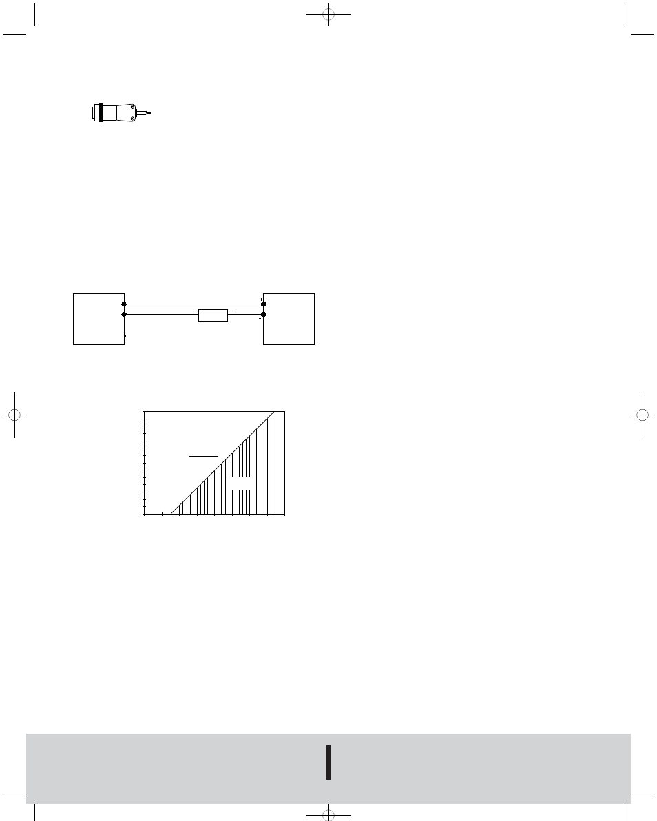
Two (2)-Wire Operation
An external power supply delivering 8 to 38 Vdc with minimum current
capability of 40 mA DC (per transmitter) is required to power the control
loop. The range of appropriate receiver load resistance for the DC power
supply voltage available is expressed by the formula and graph below.
Shielded two wire cable is recommended for control loop wiring.
PRESSURE
TRANSMITTER
POWER
SUPPLY
8-38 VDC
RED WIRE
BLACK WIRE
RECEIVER
2-WIRE CONNECTION
1400
1500
1300
1200
1100
1000
900
800
700
600
500
400
300
200
100
0
5
10
15
20
25
30
35
40
VDC
R MAX= Vps-8.0
20 mA DC
L
RECEIVER RESIST
ANCE (
Ω
)
Operating
Range
POWER SUPPLY VOLTAGE - VDC
P-4-655A:TEMPLATE 2/26/09 3:05 PM Page 2