Dwyer instruments, inc – Dwyer 631B User Manual
Page 2
©Copyright 2011 Dwyer Instruments, Inc.
Printed in U.S.A. 2/11
FR# 01-443311-00 Rev. 4
DWYER INSTRUMENTS, INC.
Phone: 219/879-8000
www.dwyer-inst.com
P.O. BOX 373 • MICHIGAN CITY, INDIANA 46361, U.S.A.
Fax: 219/872-9057
e-mail: [email protected]
ELECTRICAL CONNECTIONS
CAUTION: Do not exceed specified supply voltage ratings. Permanent
damage not covered by warranty will result. This unit is not designed for
120 or 240 volt AC line operation.
Wire Length - The Maximum length of wire connecting transmitter and
receiver is a function of wire size and receiver resistance. Wiring should
not contribute to more than 10% of receiver resistance to total loop
resistance. For extremely long runs (over 1000 ft.), choose receivers
with higher resistance to minimize size and cost of connecting leads.
When the wiring length is under 100 feet, lead wire as small as 22 AWG
can be used.
Current (4-20 mA) Output Operation - An external power supply
delivering 10-35 VDC with minimum current capability of 40 mA DC (per
transmitter) must be used to power the control loop. See Figure B for
connection of the power supply, transmitter, and receiver. The range of
the appropriate receiver load resistance (RL) for the DC power supply
voltage available is expressed by the formula:
RL Max = Vps – 10
20 mA DC
Shielded two wire cable is recommended for control loop wiring. If
grounding is required use negative side of control loop after receiver, see
Figure B.
MULTIPLE RECEIVER INSTALLATION
An advantage of the standard 4-20 mA DC output signal provided by the
Series 631 Differential Transmitter is that any number or receivers can
be connected in series in the current loop. Thus, an A-701 digital
readout, an analog panel meter, a chart recorder, process controlling
equipment, or any combination of these devices can be operated
simultaneously. It is necessary only that each be equipped with a
standard 4-20 mA input and proper polarity of the input connections be
observed when inserting the device into the current loop. If any of the
receiving devices displays a negative or downscale reading this
indicates that the signal input leads are reversed.
MOUNTING OPTIONS
MAINTENANCE
Upon final installation of the Series 631 Differential Pressure Transmitter
and the companion receiver, no routine maintenance is required. A
periodic check of the system calibration is recommended. The Series
631 Differential Pressure Transmitter is not field serviceable and should
be returned if repair is needed (field repair should not be attempted and
may void warranty). Be sure to include a brief description of the problem
plus any relevant application notes. Contact customer service to receive
a return goods authorization number before shipping.
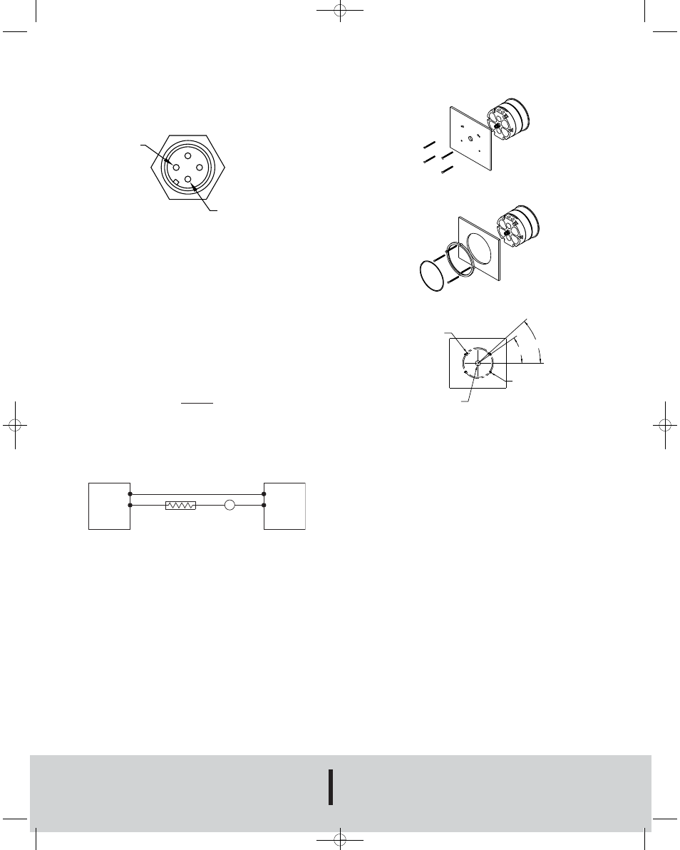
Fig. A
SERIES 631
PRESSURE
TRANSMITTER
POWER
SUPPLY
10-35 VDC
RECEIVER
1
2
+
+
–
–
mA
Fig. B
Bulletin E-114
+
–
1
4
3
2
1/4 (6.35) HOLES IN PANEL
FOR BLOWOUT PASSAGE
3/4 (19.05) HOLE IN PANEL
FOR ELECTRICAL CONNECTION
42
° - TYP 2 PLACES
35
°
(4) 3/16 (4.76) HOLES IN PANEL
EQUALLY SPACED ON A
4-11/32 (110.33) B.C.
SURFACE MOUNT HOLE PATTERN
E-114:E-114 2/7/11 1:32 PM Page 2