Dwyer MS User Manual
Series ms magnesense, Differential pressure transmitter, Dwyer instruments, inc
DWYER INSTRUMENTS, INC.
Phone: 219/879-8000
www.dwyer-inst.com
P.O. Box 373 • Michigan City, IN 46361-0373, U.S.A.
Fax: 219/872-9057
e-mail: [email protected]
The Series MS Magnesense
®
Differential Pressure Transmitter is an
extremely versatile transmitter for monitoring pressure and air velocity.
This compact package is loaded with features such as: field selectable
English or metric ranges, field upgradeable LCD display and the ability
to select a square root output for use with pitot tubes and other similar
flow sensors. Also, a single digital push button simultaneously calibrates
both zero and span reducing installation and setup time. These features
along with exceptional long term performance enables the Magnesense
®
to be the solution for a myriad of pressure and air flow applications.
INSTALLATION
Mounting:
The transmitter should be mounted on a vertical surface with the
connections directed down to prevent moisture from entering either the
pressure ports or the electrical cable entry.
Mount the transmitter using #8 x 1/2˝ pan head sheet metal screws in the
mounting flanges. Do not over tighten.
Electrical Connection:
2-Wire Operation:
Series MS Magnesense
®
Differential Pressure Transmitter
Specifications - Installation and Operating Instructions
Bulletin A-26P
SPECIFICATIONS
Service: Air and non-combustible, compatible gases.
Wetted Materials: Consult factory.
Accuracy: ±1% @ standard conditions.
Stability: ±1% F.S./ year.
Temperature Limits: 0 to 150°F (-18 to 66°C).
Pressure Limits:
1 psi (6.89 kPa) maximum, operation;
10 psi (68.9 kPa), burst.
Power Requirements:
2-wire, 10 to 35 VDC;
3-wire, 17 to 36 VDC or isolated 21.6 to 33 VAC.
Output Signals:
2-wire, 4 to 20 mA;
3-wire, 0 to 10 V or 0 to 5 V.
Response Time: 300 msec.
Pressure Calibration: One digital push button set both zero & span
simultaneously.
Loop Resistance:
Current output: 0 to 1250 ohm max.;
Voltage output: min. load resistance 1 k ohmΩ.
Current Consumption: 40 mA max.
Display (optional): 4 digit LCD.
Electrical Connections:
4 to 20 mA units: 2-wire: European style terminal block for
16 to 26 AWG;
0 to 10 V units: 3-wire: European style terminal block 16 to 22 AWG.
Electrical Entry: 1/2˝ NPS thread.
Accessory: A-151 cable gland for 5 to 10 mm diameter cable.
Process Connections: 3/16˝ (5 mm) ID tubing. Maximum OD 9 mm.
Enclosure Rating: NEMA 4X (IP65).
Mounting Orientation: Insensitive to mounting orientation.
Weight: 8.0 oz (230 g).
Agency Approval: CE.
The following standards were used for CE approval:
CENELEC EN 61000-4-2: 2001
CENELEC EN 61000-4-3: 2002
CENELEC EN 61000-4-4: 1995
CENELEC EN 61000-4-5: 2001
CENELEC EN 61000-4-6: 2003
CENELEC EN 61000-4-8: 2001
CENELEC EN 55011: 2003
CENELEC EN 61326: 2002
89/336/EED EMC Directive
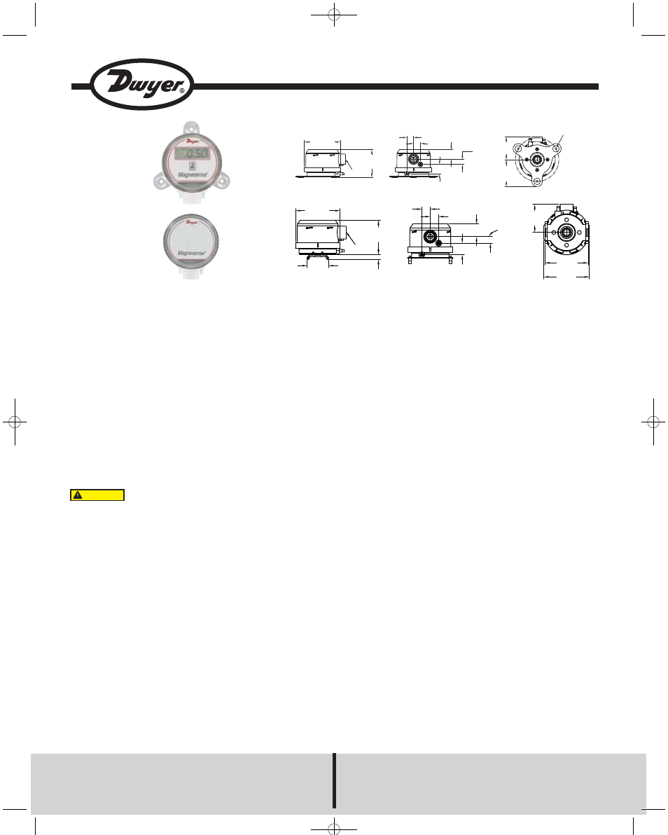
Ш3-7/16
[Ш87.31]
2-41/64
[67.07]
1/2 NPT
21/32
[16.67]
21/32
[16.67]
29/32
[23.02]
1/2
[12.70]
57/64
[22.62]
(3) 3/16 [4.76] HOLES
EQUALLY SPACED ON A
4.115 [104.52] BC
2-11/64
[55.17]
2-9/16
[65.09]
DO NOT EXCEED SPECIFIED SUPPLY VOLTAGE
RATINGS. PERMANENT DAMAGE NOT COVERED BY
WARRANTY WILL RESULT. 2-WIRE UNITS ARE NOT DESIGNED FOR AC
VOLTAGE OPERATION.
CAUTION
ш3-7/16
[Ш87.31]
1/2 NPT
25/64
[9.96]
1-41/64
[41.71]
2-41/64
[67.24]
21/32
[16.67]
57/64
[22.62]
21/32
[16.67]
29/32
[23.02] 1/2
[12.70]
2-11/64
[55.17]
3-11/32
[84.84]
3-1/2
[88.90]
Wall Mount Bracket
DIN Mount Bracket
A-26P:Magnesense bulletin 2/21/11 12:13 PM Page 1