Dwyer instruments, inc – Dwyer 636D User Manual
Page 2
©Copyright 2014 Dwyer Instruments, Inc.
Printed in U.S.A. 5/14
FR# R6-443317-00 Rev. 2
DWYER INSTRUMENTS, INC.
Phone: 219/879-8000
www.dwyer-inst.com
P.O. BOX 373 • MICHIGAN CITY, INDIANA 46360, U.S.A. Fax: 219/872-9057
e-mail: [email protected]
INSTALLATION
Care should be taken during installation to prevent condensate accumu-
lation in the conduit compartment or sediment accumulation in the
diaphragm chambers. It is good practice to install the transmitter with the
conduit connection pointing down or to utilize a conduit drain or drip leg
where this is not possible. Calibration of this transmitter is performed
with the process connections in the horizontal plane. The specified worst
case inaccuracies due to mounting orientation would occur when the
process connections are in the vertical plane. A pipe joint compound or
pipe thread sealant tape thread should be used to assure a leak-proof
process connection.
ELECTRICAL CONNECTIONS
CAUTION: Do not exceed specified supply voltage rating. Permanent
damage not covered by warranty will result. This unit is not designed for
AC line voltage operation. Power must be off while wiring connections
are being made.
An external power supply delivering 12-30 VDC with a minimum current
capability of 40 mA DC (per transmitter) or 8-14 VDC when using a 1-5
VDC output model, must be used to power the control loop. See Fig. A.
To comply with good electrical practice, it is recommended that the trans-
mitter be grounded. This can be accomplished through either the green
wire or the transmitter case. To avoid a “ground loop” condition, DO NOT
use both. The shield/drain wire is not connected to the case. This
shield/drain is normally tied to ground at the receiver for optimal noise
rejection.
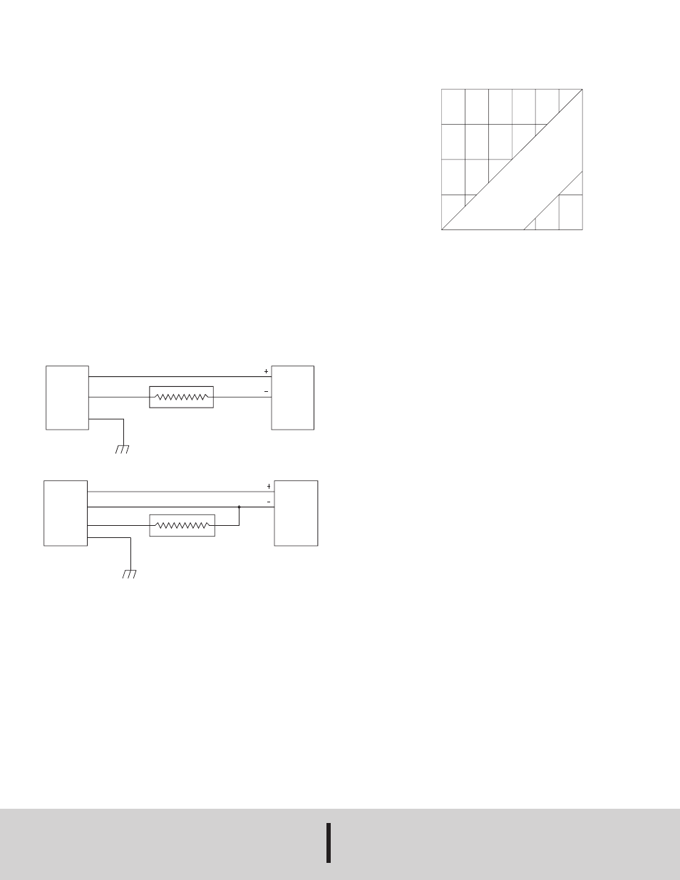
The range of appropriate loop resistance, including the receiver load
resistance for the DC power supply being used is limited to that
expressed by the graph in Fig. B.
MAINTENANCE
Upon final installation of the Series 636D Fixed Range Differential
Pressure Transmitter and the companion receiver, no routine mainte-
nance is required. A periodic check of the system calibration is recom-
mended. The Series 636D Fixed Range Differential Pressure
Transmitter is not field serviceable and should be returned if repair is
needed (field repair should not be attempted and may void warranty). Be
sure to include a brief description of the problem plus any relevant appli-
cation notes. Contact customer service to receive a return goods autho-
rization number before shipping.
Fig. A
Fig. B
SERIES
636D LP
PRESSURE
TRANSMITTER
POWER
SUPPLY
12-30 VDC
RED
BLACK
WHITE
GREEN
RECEIVER
SERIES 636D
PRESSURE
TRANSMITTER
POWER
SUPPLY
12-30 VDC
RED
BLACK
GREEN
RECEIVER
900
675
450
225
0
12
15
18
21
24
27
30
SUPPLY VOLTAGE (VDC)
L
O
O
P
R
E
S
IS
T
A
N
C
E
(
O
H
M
S
)
OPERATING
RANGE
4-20 mA Output
Voltage Output