Dwyer instruments, inc – Dwyer 608 User Manual
Page 2
©Copyright 2009 Dwyer Instruments, Inc.
Printed in U.S.A. 7/09
FR# R1-443350-00 Rev. 1
DWYER INSTRUMENTS, INC.
Phone: 219/879-8000
www.dwyer-inst.com
P.O. BOX 373 • MICHIGAN CITY, INDIANA 46361, U.S.A.
Fax: 219/872-9057
e-mail: [email protected]
2. Position: The Series 608 Transmitter is not position sensitive.
However, it is recommended that you avoid mounting with pres-
sure connections pointing up because of the chance of con-
densed moisture entering the interior. Moisture can also be avoid-
ed by routing tubing with a low point just ahead of the transmitter.
3. Mounting: Attach to mounting surface with two #8 or #10
screws in the mounting slots provided.
4. Pressure Connections: The 608 series transmitter is shipped
with the “HIGH” and “LOW” pressure ports plugged to avoid
debris entering the unit. The plugs should be left in place until the
tubing and fittings are connected. For gage pressures, connect
positive (above atmospheric) pressure to the port marked “HIGH”
and vent the “LOW” port. To monitor vacuum, connect negative
(vacuum) pressure to port marked “LOW” and vent the “HIGH”
port. For differential pressure, connect the higher one to the
“HIGH” port and the lower one to the “LOW” port.
ELECTRICAL CONNECTION
Use in hazardous location: The Series 608 transmitter is FM
approved intrinsically safe for use in hazardous locations. See
specifications for details. Intrinsically safe approved devices require
the use of an approved intrinsic safety barrier when applied in haz-
ardous locations. The barrier limits the amount of electrical or ther-
mal energy in the instrument loop, to the level which would not
cause ignition in the hazardous location for which it is rated. The
barrier must be installed outside of the hazardous area and prop-
erly wired to the transmitter according to Figure B.
CAUTION: Do not exceed the specified supply voltage rating.
Permanent damage, not covered by warranty, may result. This unit
is not designed for AC voltage operation.
The terminal connections can be accessed by unscrewing the four
cover screws and removing the terminal block access cover. Bring
cable wires in through one of the 1/2˝ female NPT conduit con-
nections, plugging the unused entry. Attach the cable wires to the
appropriate terminals. If polarity is inadvertently reversed, the loop
will not function properly but no damage will be done to the trans-
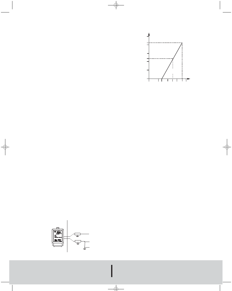
mitter because of internal circuit protection. The power required to
generate the 4-20 mA output signal depends on the loop resis-
tance of the circuit and is proportional to the resistance according
to the graph and formula in Figure C. The maximum length that
can be used in the current loop is a function of wire size and
receiver resistance. A shielded two conductor cable is recom-
mended for control loop wiring. Make sure total loop resistance is
within the operating region as shown in Figure C.
V
min
= 12V + (.022A x R
L
)
R
L
= R
S
+ R
W
R
L
= Loop Resistance (ohms)
R
S
= Sense Resistance (ohms)
R
W
= Wire Resistance (ohms)
CALIBRATION
Each Series 608 Transmitter is factory calibrated to the range list-
ed in the model number chart. Range is defined as that pressure
which when applied to the transmitter will produce a 20 milliamp
current in the loop. Zero pressure will produce 4 milliamps. If fine
adjustment of calibration is required, use the following procedure:
1. With the transmitter connected to its companion receiver, insert
a milliammeter in series with the current loop. A controllable pres-
sure source should be tied to the high pressure port of the trans-
mitter and to an accurate pressure gage or manometer.
2. Apply electrical power to the system and allow 15 seconds for
components to stabilize.
3. With no pressure applied to the transmitter remove cover and
adjust “zero” control so loop current is at 4 mA.
4. Apply full span pressure and adjust loop current to 20 mA using
“span” control.
5. Remove the milliammeter from the circuit, replace cover, and
place system in service.
MAINTENANCE
After final installation of the Series 608 Differential Pressure
Transmitter, no routine maintenance is required. A periodic check
of system calibration is suggested. These devices are not field
repairable and should be returned if repair is needed (field repair
should not be attempted and may void warranty). Be sure to
include a brief description of the problem plus any relevant appli-
cation notes. Contact customer service to receive a return goods
authorization number before shipping.
Fig. C
Bulletin E-60
1250
1045
1000
750
545
500
250
0
0
10 12
20 24 30
36 40
OPERATING
REGION
LOOP RESISTANCE (Ω)
LOOP SUPPLY VOLTAGE (VDC)
Load Limitations 4-20 mA Output Only
Fig. B
HAZARDOUS AREA
SAFE AREA
ENTITY APPROVED
BARRIERS
SUPPLY
RETURN
E-60:E-60 7/13/09 2:13 PM Page 2