Operation, Maintenance – Dwyer 645 User Manual
Page 2
DWYER INSTRUMENTS, INC.
P.O. Box 373, Michigan City, Indiana 46360, U.S.A.
Phone: 219/879-8000
Fax: 219/872-9057
FR R1-440983-00
©Copyright 1997 Dwyer Instruments, Inc.
Printed in U.S.A. 7/97
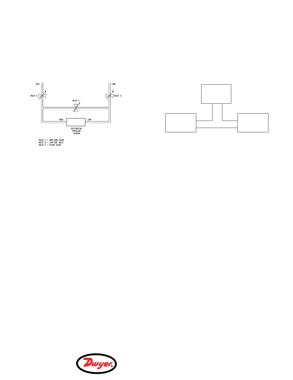
NOTE:
For differential pressure measurements at high line pres-
sure (250 psig max.), it is recommended that the pres-
sure sensor be installed with a valve in each line, plus a
shunt valve across the high and low (reference) pressure
ports as indicated in Figure 2 below. The high pressure
port is labeled with the word “HIGH”.
Valve C should be open and Valves A and B closed
whenever the system is first being wetted or pressur-
ized. Valves A and B should then be opened slowly to
avoid hammering. Valve C can then be closed and the
system is operating. When removing the differential
pressure sensor, open Valve C first, then close Valves A
and B.
Bleeding the Pressure Ports
Three bleed screws are located on the side of the unit
(two for low pressure port, one for high pressure port).
Install the transmitter in its intended location and pres-
surize the ports. Back off the first bleed screw mounted
on the flat side of the sensor body (2 turns max.) until liq-
uid begins to flow out. After only bubble-free liquid flows
out, retighten the bleed screw. Repeat the same proce-
dure for the second set of bleed screws located on the
round section of the low pressure fitting.
Electrical Connections
The Series 645 Wet/Wet Differential Pressure
Transmitters are true 2-wire, 4-20 mA current output
devices and deliver rated current into any external load
of 0 to 800 ohms.
The units are supplied with a 7/8
″ diameter knockout
intended for a 1/2
″ ID conduit connection. It is suggest-
ed that any electrical cable shield be connected to the
system’s loop circuit ground to improve electrical noise
reduction.
When making electrical connections, be sure to observe
polarity—units are designed to have current flow in one
direction only. The minimum supply voltage is 11 +.02
ϫ
(Resistance of receiver plus line. The maximum supply
voltage is 30 + .004
ϫ (Resistance of receiver plus line).
To access electrical connections, remove cover on top
of the unit. See Figure 3 for correct electrical connec-
tions.
OPERATION
The Series 645 Wet/Wet Differential Pressure
Transmitters are carefully calibrated to the specific input
pressure range versus current output at the factory. Little
or no field calibrating is necessary.
Zero and Span Adjustment
To gain access to the zero and span adjustments,
remove the top cover of the transmitter. Loosen the 6-32
seal screws in the plastic terminal block. The zero and
span adjustments are located under the plastic terminal
block. Be careful not to disconnect any internal wiring.
After all adjustments are made, remember to re-install
the 6-32 seal screws. The Series 645 transmitters with
4-20 mA output are factory calibrated using a 250 ohm
load at 24 VDC. Zero and span adjustments are approx-
imately ±1 mA, individually.
MAINTENANCE
After final installation of the Series 645 Wet/Wet
Differential Pressure Transmitter, no routine maintenance
is required. Periodic checks of connections is recom-
mended. Please contact Dwyer Instruments, Inc. before
returning unit for repair to review information relative to
your application. When returning a product to the facto-
ry, carefully package and ship freight prepaid. Be sure to
include a complete description of the application and
problem and identify any hazardous material used with
the product.
Series 645
Transmitter
Power
Supply
Load
(Monitor)
+
+
+
-
-
-
Figure 3
Figure 2
Wiring
System Set-up
R1-700442-01