Dwyer instruments, inc – Dwyer 607 User Manual
Page 2
©Copyright 2013 Dwyer Instruments, Inc.
Printed in U.S.A. 5/13
FR# 01-440685-00 Rev. 1
DWYER INSTRUMENTS, INC.
Phone: 219/879-8000
www.dwyer-inst.com
P.O. BOX 373 • MICHIGAN CITY, IN 46360, U.S.A.
Fax: 219/872-9057
e-mail: [email protected]
INSTALLATION
1. Location: Select a clean, dry location free of excess vibration where the
temperature of the unit with be between -20 and 160°F. Distance from the
receiver is limited only by total loop resistance. See “ Electrical Connections”. The
tubing supplying pressure to the transmitter can be run practically any distance.
Long tubing lengths will not affect accuracy but response time will be increased
slightly.
2. Position: The Series 607 Transmitter is not position sensitive. However, it is
recommended that you avoid mounting with pressure connections pointing up
because of the chance of condensed moisture entering the interior. Moisture can
also be avoided by routing tubing with a low point just ahead of the transmitter.
3. Mounting: Attach to mounting surface with two #8 or #10 screws in the
mounting slots provided.
4. Pressure connections: The Series 607 Transmitter is shipped with a short
length of tubing installed between the ports to keep the interior clean. Remove it
and discard after unit is mounted. Connect positive (above atmospheric) pressure
to port marked “HIGH and vent the “LOW” port. Connect negative (vacuum)
pressure to port marked “LOW” and vent the “HIGH” port. For differential
pressures, connect the higher one to the “HIGH” port and the lower one to the
“LOW” port.
ELECTRICAL CONNECTION
Caution: Do not exceed the specified supply voltage rating. Permanent damage,
not covered by warranty, may result. This unit is not designed for AC voltage
operation.
Electrical connections to the Series 607 Transmitter are made to the two screws
on the terminal strip labeled + and -. If polarity is inadvertently reversed, the loop
will not function properly but no damage will be done to the transmitter because
of internal circuit protection. An external power supply delivering 12 to 36 VDC
must be used to power the control loop in which the transmitter is connected.
Refer to Figure B for connection of the power supply, transmitter and receiver.
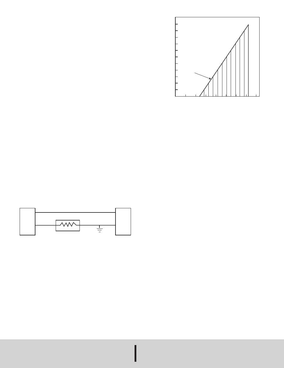
The power required to generate the 4-20 mA output signal depends on the loop
resistance of the circuit and is proportional to the resistance according to the
graph and formula in Figure C. The maximum length that can be used in the
current loop is a function of wire size and receiver resistance. A shielded two
conductor cable is recommended for control loop wiring. Make sure the total loop
resistance is within the operating region as shown in Figure C.
CALIBRATION
Each Series 607 Transmitter is factory calibrated to the range listed in the model
number chart. Range is defined as that pressure which when applied to the
transmitter will produce a 20 milliamp current in the loop. Zero pressure will
produce 4 milliamps. If fine adjustment of calibration is required, used the
following procedure:
1). With the transmitter connected to its’ companion receiver, insert a
milliammeter in series with the current loop. A controllable pressure source should
be teed to the high pressure port of the transmitter and to an accurate pressure
gage or manometer.
2). Apply electrical power to the system and allow 15 seconds form components
to stabilize.
3). With no pressure applied to the transmitter remove blowout disc and adjust
“zero” control so loop current is 4 mA.
4). Apply full span pressure and adjust loop current to 20 mA using “span” control.
5). Remove the milliammeter from the circuit, replace blowout disc, and place
system in service.
MAINTENANCE/REPAIR
After final installation of the Series 607 Differential Pressure Transmitter, no
routine maintenance is required. A periodic check of system calibration is
recommended. These devices are not field repairable and should be returned to
the factory if recalibration or other service is required. After first obtaining a
Returned Goods Authorization (RGA) number, send the material, freight prepaid,
to the following address. Please include a clear description of the problem plus
any application information available.
Dwyer Instruments, Inc.
Attn: Repair Department
102 Highway 212
Michigan City, IN 46360.
NOTE: RECEIVER MAY BE IN
SERIES WITH + or -
LEG OF CONTROL LOOP
POWER
SUPPLY
12-36 VDC
SEE FIG. C
RECEIVER (R
L
)
GROUND
OPTIONAL
SERIES 607
PRESSURE
TRANS-
MITTER
+
-
+
-
Figure B
1100
1000
900
800
700
600
500
400
300
200
100
0
L
O
O
P
R
E
S
IS
T
A
N
C
E
(
Ω
)
OPERATING RANGE
V
MIN
= 12V + (.022A x R
L
)
MAXIMUM VALUE (1090)
0 5 10 12 20 25 30 36 40
POWER SUPPLY VOLTAGE - VDC
Figure C