Dwyer instruments, inc, Adjustment, Maintenance – Dwyer 1996 User Manual
Page 2
3. Remove the snap-on cover from the conduit
enclosure by loosening its retaining screw and pulling
firmly on its set screw held end. Electrical terminals for
all switches are marked Common, Normally Open, and
Normally Closed. The switch is not actuated until
pressure is applied. On rising pressure, the switch actu-
ates and Normally Open contacts close. Should gas
pressure fail, the switch (when set for low gas pressure)
will de-actuate and the Normally Open contacts re-open.
When set for high gas pressure (regulator failure) the
switch will actuate (and Normally Closed contacts will
open) when overpressure occurs. Wire switch accord-
ingly: make sure load doesn't exceed electrical ratings.
Use flexible or rigid conduit to enclose wires to switch.
4. Adjust the set point following instructions under
adjustment.
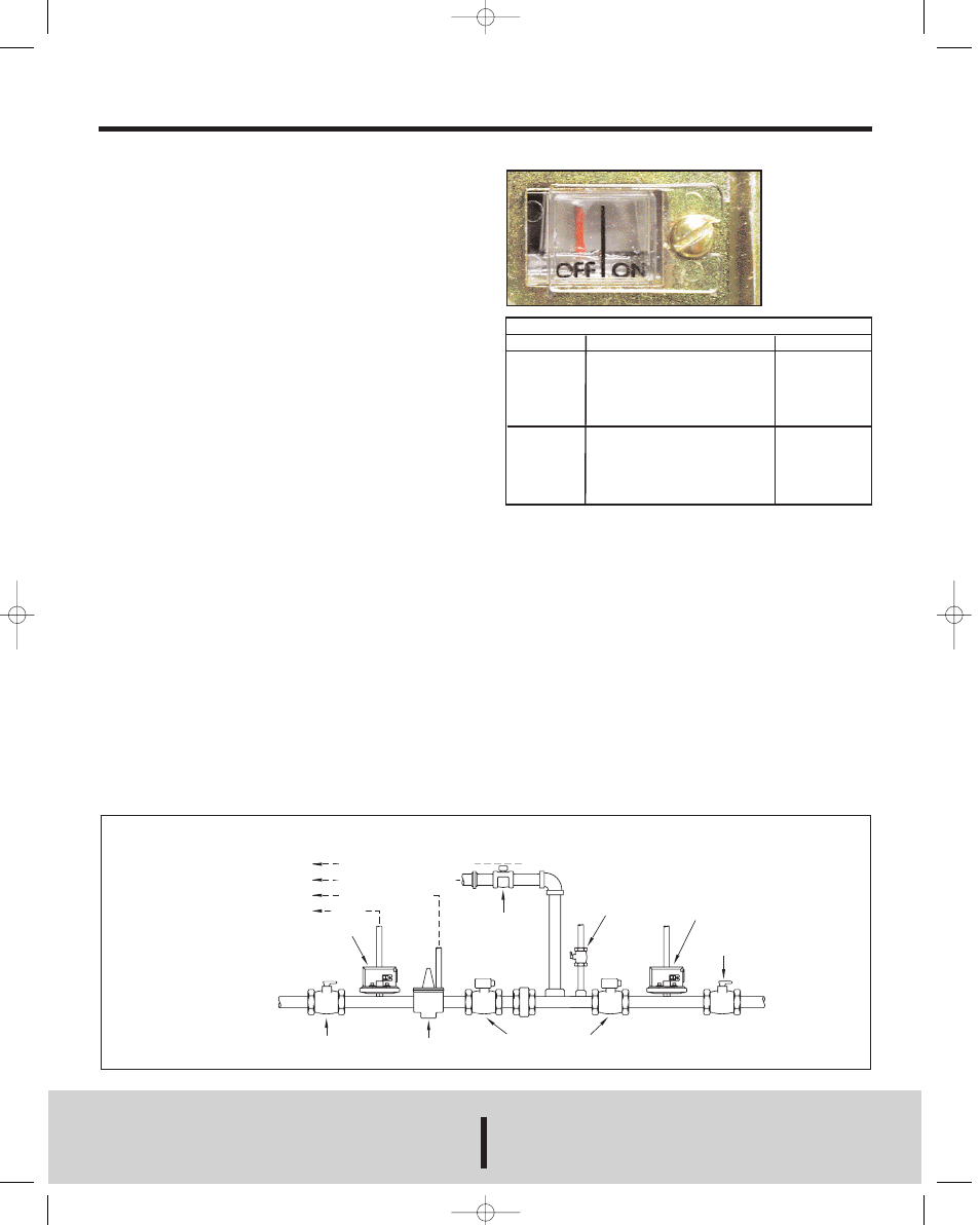
5. Check carefully for leaks. Be sure that switch set
point and installation complies with the furnace/burner
manufacturer’s instructions. Watch the On-Off indicator
in window to observe proper operation.
ADJUSTMENT
1. To change the set point, remove the cover from the
conduit enclosure. Turn the slotted Adjustment Screw at
the end of the range spring housing clockwise to raise
the set point pressure and counter-clockwise to lower
the set point. The visible set point indicator shows the
set point from 4 (min) to 20 (max) inches w.c. for Model
1996-20 and 1.5 (min) to 5 (max) inches w.c. for Model
1996-5.
2. (a) For high gas pressure applications, to actuate on
regulator failure, adjust the set point so that desired set-
ting (normally 1
″ or 12″ above operating pressure)
shows in the window.
(b) For low gas pressure applications, to actuate on gas
DWYER INSTRUMENTS, INC.
Phone: 219/879-8000
www.dwyer-inst.com
P.O. BOX 373 • MICHIGAN CITY, INDIANA 46361, U.S.A.
Fax: 219/872-9057
e-mail: [email protected]
Lit-By Fax: 888/891-4963
Series 1996 – Natural and L.P. Gas Pressure Switches
Specifications - Installation and Operating Instructions
Bulletin E-58
Page 2
©Copyright 2000 Dwyer Instruments, Inc.
Printed in U.S.A. 6/00
FR # 26-440252-00 Rev. 1
Visible on-off
pointer indi-
cates actuation
or de-actuation
of switch. This
permits instant
trouble-shoot-
ing of electrical
circuit or gas
supply.
Motorized
Gas Valves
Typical Piping Diagram for Gas-Fired Furnaces
(Pilots Not Shown)
Low Pressure
Gas Switch
Vent outside
separately or to
combustion chamer
per manufacturer's
instructions.
Gas
Supply
Main Gas
Shut-Off Valve
Gas Pressure
Regulator
Solenoid
Vent Valve
(Normally Open)
Test
Cock
High Pressure
Gas Switch
Checking
Gas Cock
To Main
Burner
Inches in Water Column
Set Point Approximate Dead Band Reset Point
Model 1996-5
1.5
0.10
1.30
2
0.12
1.88
3
0.14
2.86
4 0.17 3.83
5
0.19
4.81
Model 1996-20
4
0.15
3.85
5
0.15
4.85
10
0.24
9.76
15
0.33
14.67
20
0.41
19.59
pressure failure, adjust the set point slightly below
(usually 2
″ or 1″ w.c.) the normal gas pressure.
De-actuation will occur at set point pressure minus the
dead band. See chart below.
MAINTENANCE
The moving parts of these switches are sealed in and are
permanently tamper-proof. The single adjustment is that
of the set point. Care should be taken to keep the switch
reasonably dry and free from dust or dirt. No lubrication
or unusual precautions are required for
normal use.
new E-58 REV 1 6/24/02 8:47 AM Page 2