F-2000, Page 8, Caution: disconnect power source before servicing – Blue-White F-2000 – Sensor User Manual
Page 9: Page 9, 3 model rt circuit board wiring
F-2000
Page 8
Option A: 1 / 2-14 MPT
Red Cap Plug
(for pipe fitting)
Option B: 1/2 DIA.
Knock-out
(small liquid-tight connector)
Option B: 3/4 DIA.
Knock-out
(large liquid-tight connector)
Option A: Conduit Connection
1. Remove the red cap plug.
2. Install your pipe fitting (1/2 - 14 NPT male
end).
Option B: Liquid-Tight Connections
1. Remove knock-out(s) using a screwdriver.
2. Trim edge(s) with a knife and remove sharp
edges.
3. Install the provided liquid-tight connector(s).
Notes:
For the large liquid-tight connector (3/4” knock-out), the acceptable cable diameter is between .200 - .394 in (5.1 -
10.0 mm).
For the small liquid-tight connector (1/2” knock-out), the acceptable cable diameter is between .118 - .255 in (3.0 -
6.5 mm).
Internal V
iew
6.0
F-2000 Electrical Wiring Connections
6.1 Enclosure knock-out Instructions
6.2 Optional Circuit Board Installation
1.
Carefully align optional board’s Pin
Header with the Pin Header socket
located on the main circuit board.
2.
Press firmly into place.
3.
Secure the board with the two screws
provided.
F-2000
Enclosure
Cover
N.C.
N.O.
C
F-2000-PC
(OPTIONAL
BOARD)
F-2000-AO
(OPTIONAL
BOARD)
F-2000-R
T
(MAIN BOARD)
CAUTION: DISCONNECT POWER
SOURCE BEFORE SERVICING.
F-2000
Page 9
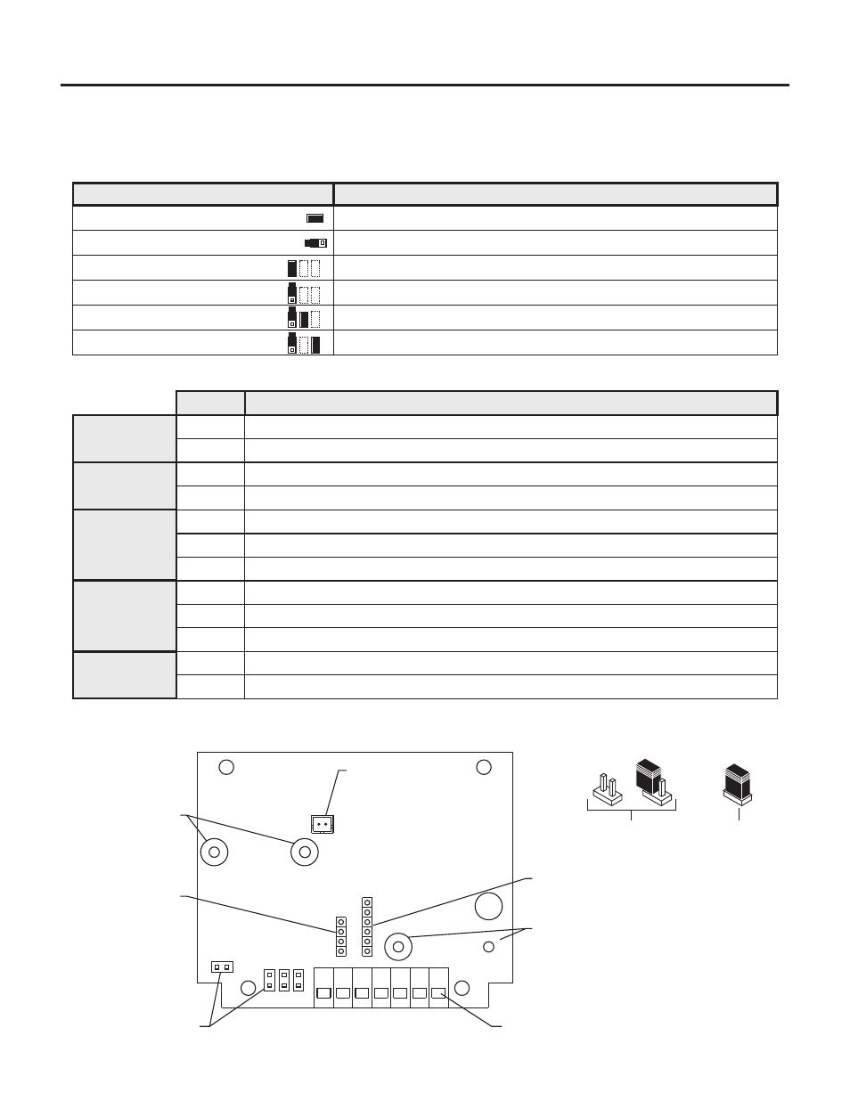
Jumpers
J1 Installed
J1 Left Open
J2 Installed
J2 Left Open
J3 Installed and J4 Left Open
J3 Left Open and J4 Installed
Function
Battery Input (4 - 1.5 VDC, AA Cells)
Plug-In Transformer (115 VAC / 15 VDC, 220 VAC / 15 VDC, 230 VAC / 15 VDC)
Front Panel Programming is Disabled
Front Panel Programming is Enabled (factory default)
Hall Effect Sensor and Micro-Flow Sensor Input
AC Coil Sensor Input
J3
J2
J4
J1
7 6 5 4 3 2 1
Jumpers
SIP Socket for
F-2000 PC Board
SIP Socket for
F-2000 AO Board
Backup Battery
Connector
Terminal Blocks
F-2000 RT Board
F-2000 PC Board
Mounting Screw
Bushings
F-2000 AO Board
Mounting Screw
Bushings
Jumper Configuration
BA
T
= ON
P H M
Jumper Not
Installed (open)
Jumper
Installed
Jumper Positions
6.3 Model RT Circuit Board Wiring
CAUTION: DISCONNECT POWER SOURCE BEFORE SERVICING.
Terminal Function
6
2
3
1
2
3
7
4
Supply power
input
AC coil sensor
input
Hall Effect
sensor input
Open connector
pulse output
(from sensor)
Positive (+) power input (red wire from battery pack, or black with stripe wire from 15 VDC plug-in transformer)
Ground (-) power input (black wire from battery pack or 15 VDC plug-in transformer)
Ground (-) input (black wire from coil sensor body)
Pulse input (yellow or red wire from coil sensor body)
Positive (+) input (red wire from hall effect sensor)
Ground (-) input (black wire from hall effect sensor)
Pulse input (bare wire from hall effect sensor)
NPN positive (+) signal output
NPN negative (-) signal output
Terminal Configuration
5
(Max voltage: 30VDC, Max load: 15mA, 2k ohm pull-up recommended.)
1
2
3
Micro-Flo
sensor input
Positive (+) input (red wire from hall effect sensor)
Ground (-) input (black wire from Micro-Flo sensor or negative (-) output from Micro-Flo display circuit board)
Pulse input (bare wire from Micro-Flo sensor or positive (+) output from Micro-flo display circuit board)