Caution – Blue-White CHEM-PRO C3 ProSeries Diaphragm Pump User Manual
Page 7
Page 6
4.1
Mounting Location
Choose an area located near chemical supply tank, chemical injection point, and electrical supply. Install pump
where it can be easily serviced.
316SS Mounting brackets are included. Mount pump to a secure surface using enclosed mounting hardware.
Mount pump close to injection point. Keep inlet (suction) and outlet (discharge) tubing as short as possible.
Longer discharge tubing increases back pressure at pump head.
Important! Install a back flow prevention check valve at discharge side of pump to prevent system fluid from
flowing back through pump during pump maintenance. Important!
A pressure relief valve is recommended at discharge of pump.
4.2
Dimensions
All diagrams are strictly for guideline purposes only. Always consult an expert before
installing metering pump on specialized systems. Metering pump should be serviced by
qualified persons only.
!
Always wear protective clothing, face shield, safety glasses and gloves when working on or
near your metering pump. Additional precautions should be taken depending on solution
being pumped. Refer to MSDS precautions from your solution supplier.
Risk of chemical overdose. Be certain pump does not overdose chemical during backwash
and periods of no flow in circulation system.
CAUTION
!
CAUTION
!
CAUTION
Page 7
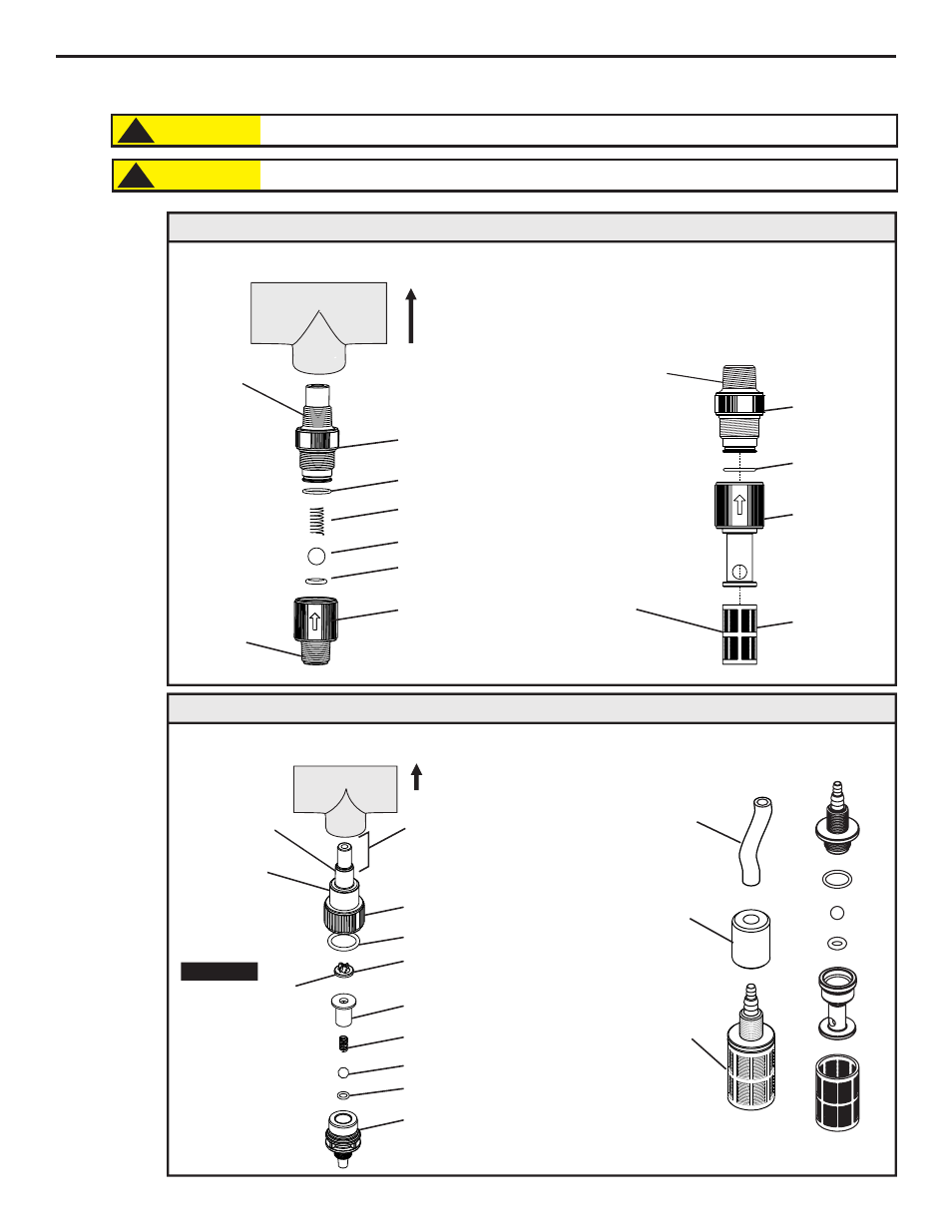
Pipe
Tee
½” male NPT
1/4” male NPT
Discharge Injection Fitting / Check Valve
Discharge Injection Fitting / Check Valve)
Pipe
Tee
Install
upward
for best
results
½” (1.3 cm)
Male NPT
½” (1.3 cm)
Male NPT
or
½” (1.3 cm)
Hose Barb
Suction Strainer
½” (1.3cm) I.D. Wetted Connection Models; Injection Fitting and Strainer
Suction Tubing and Strainer
Suction Tubing, PVC
3/8" (.95 cm) OD X
1/4” (.64 cm) ID
Duckbill - May reduce
calcium buildup when
injecting bleach.
Duckbill will add
additional back
pressure to pump (up
to 7 psi / .48 bar).
Remove duckbill to
reduce pressure or
when metering viscous
fluids.
Proper eye and skin protection must be worn when installing and servicing pump.
!
CAUTION
This Pump Has Been Evaluated for Use with Water Only.
!
CAUTION
PVDF
PVDF
O-Ring, Viton (optional EP)
O-Ring, T/FEP
(optional EP)
Spring, Hastelloy C-276
Ball, Ceramic
½” (1.3 cm)
Male NPT
or
½” (1.3cm)
Hose Barb
PVDF
PVDF
O-Ring, Viton
(optional EP)
Polypropylene
Removable
275 Micron
Filter
PVDF
Spring, Hastelloy C-276
PVDF
O-Ring, T/FEP (optional EP)
Ball, Ceramic
O-Ring, Viton (optional EP)
Duckbill, Santoprene
(optional)
PVDF
Injection Nose
may be trimmed
(removed) when
injecting into
small pipe.
Install upward
for best results
Note:
Optional Extended Bracket adds 4.5” (11.43cm) to overall height (dimension G and H). See page 3 for details.
1/4” (.64cm) I.D. Tube Wetted Connection Models; Injection Fitting and Strainer
4.0
Installation
4.3
Installing Injection Fitting and Strainer
Important!
Chem-Pro
Chem-Pro
®
®
Top
Front
Right
A
B
C
D
E
G
H
I
F
J
Inches
cm
A
B
C
D
E
12.8”
11.5”
3.7”
2.5”
11.8”
32.5
29.2
9.5
6.4
29.9
C2 Dimensions
F
7.9”
20.1
G
H
I
J
7.3”
18.4
6.5”
16.4
13.6”
34.6
8”
20.3
Dim
Inches
cm
A
B
C
D
E
14.1”
12”
3.7”
2.5”
13.1”
35.8
30.5
9.5
6.4
33.2
C3 Dimensions
F
9”
22.9
G
H
I
J
7.8”
19.8
6.5”
16.4
15”
38
8”
20.3
Dim
FootValve
Strainer
Assembly
Ceramic
Weight