Installation, Twl & spds – Advanced Protection TWL User Manual
Page 5
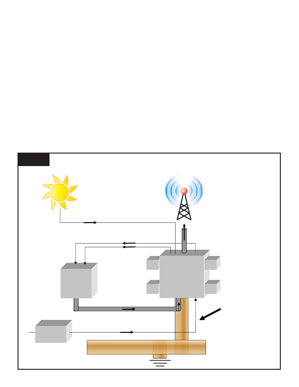
YOU WILL NEED
SUFFICIENT SPACE
FOR GROUND STRAP
TOWER
LIGHT
CONTROLLER
AC POWER
SERVICE
ENTRANCE
TWL & SPDs
Photocell Conductor
AC Power
(Now Surge Protected)
AC Power
Wire Bundle Going Up-tower
(Now Surge Protected)
4” Copper Strap
Connection to Ground
Unprotected Wire Bundle Going Up-tower
Existing Copper Strap
Ground Grid
Photocell Conductor
(Now Surge Protected)
Page 2
Figure 1
INSTALLATION
1. Verify that all correct components are in hand:
• TWL: This is effectively an assembly that SPDs attach to in a modular format.
• AC voltage SPD: Verify correct voltage and number of phases. This will mount perpendicular over the top of the two DIN
Rails. It is raised on stand offs so that wiring can pass underneath it. We recommend that this SPD be installed last so
it remains out of your way.
• Photocell SPD: Verify correct voltage. This will mount on a DIN Rail inside the TWL.
• Individual Light SPDs: Use a voltmeter to check all voltages to ensure correct SPDs.
• Verify correct voltage. Be aware that some strobe lights are DC voltage. Connecting the wrong SPDs to wrong voltages
will fail SPDs at startup.
Not included with TWL or SPDs:
• Conduit, fittings, wire, hardware, etc.
• 4” copper ground strap & ground connections
• Mounting hardware
• Labeling equipment
2. Identify appropriate mounting location for TWL (See Figure 1)
You will Need Sufficient Space on Wall for TWL & SPDs