Ac power spd – Advanced Protection TWL User Manual
Page 11
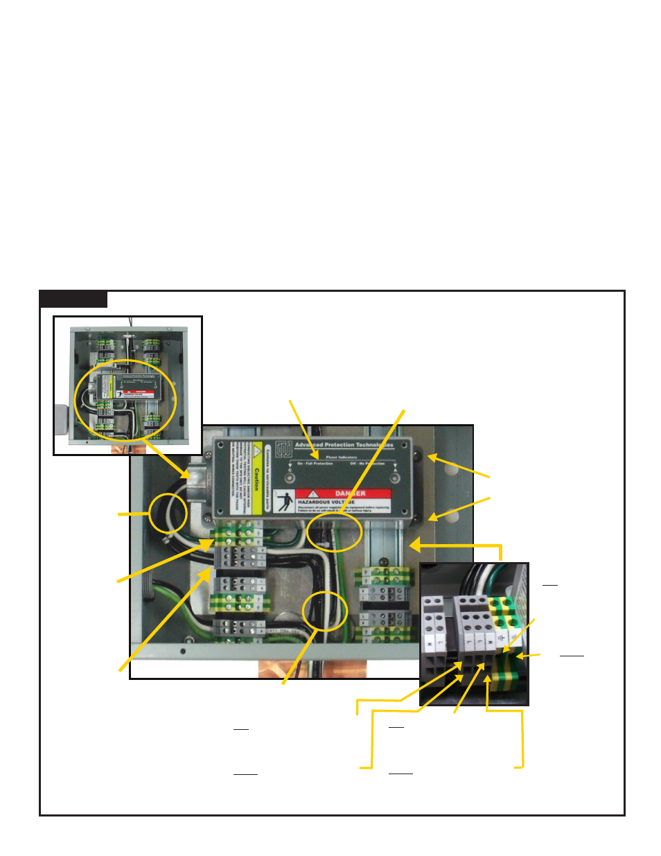
AC POWER SPD (FIGURE 7)
• We suggest installing this last because it mounts over the top of other wiring & circuitry.
• Identify the mounting standoffs. The XCS SPD will mount onto those standoffs.
• Identify the terminal blocks for AC Power SPD. These are immediately adjacent to the SPDs mounting location, and include
one extra terminal for a 120/240V application. (The other pre-configured terminals assume one hot and one neutral. AC
power presumes two hots and one neutral.)
• There may be an existing SPD at the electrical service entrance, grounded at that point. The TWL SPD serves as a
redundant, cascaded SPD, grounded in the TWL at the same point as the other tower light SPDs. Do not eliminate the
TWL AC power SPD under the presumption that the service entrance SPD provides protection.
• Read SPD installation manual.
• Mount SPD such that conductors to terminal blocks are shortest. Inches matter - do not run the conductors across the
TWL to the opposite set of DIN rail connectors. Bolt down SPD to standoffs.
• Connect SPD AC-Hot(s) to terminal block as shown in Figure 7. Torque: 7 lb-in
• Connect SPD AC-Neutral to terminal block as shown in Figure 7. Torque: 7 lb-in
• Note that both of these are feed-through connectors. The load goes in and out of the terminal. The SPD is connected
electrically in parallel, not in series.
• Connect SPD Ground to terminal block as shown in Figure 7. Torque: 7 lb-in
• Configure SPD leads as short and straight as possible. Do Not coil excess leads. Do Not create sharp kinks.
Figure 7
Page 8
Leads into terminal blocks from service entrance or AC power panel
SPD Mounting Standoffs
Leads from
terminal block
to tower light
controller AC
power input
Incoming Power APT
XCS-family SPD
(120/240V split phase
in this example)
N into terminal block from service
entrance or AC power panel
L1 & L2 into terminal block from service
entrance or AC power panel
G into one terminal
block from service
entrance or AC
power panel
G out of other
terminal block
to tower light
controller AC
power input
(Both Ground
terminal blocks are
connected together
and grounded to
DIN Rail)
N out of terminal block to tower
light controller AC power input
L1 & L2 out of terminal block to tower
light controller AC power input
Leads from SPD
to back side of
terminal block
Two Ground
Terminals are
interconnected
because they are
both grounded to
the DIN rail
SPD connects to
load conductors
via feed-through
terminal blocks
AC Power SPD