Measure – current, Power and calibrate - transmitters/sensors, Measure mode – Time Electronics 1048 Voltage-Current-Loop Calibrator User Manual
Page 8
8
V1.2 30/12/10
P a g e
| 8
1048 Technical Manual
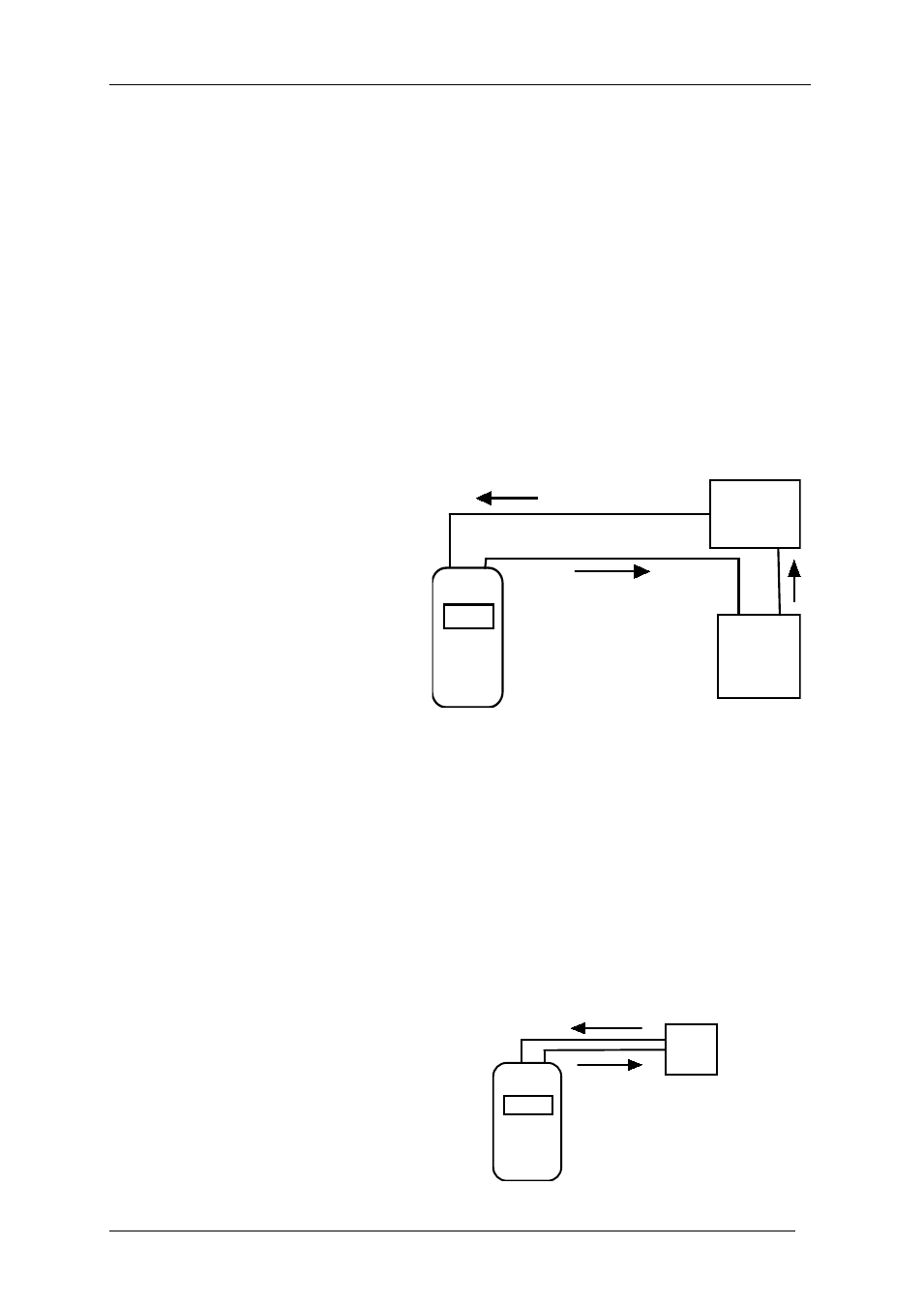
3.3. Measure – Current
The unit measures current in three selectable ranges, 0 to 0.22mA (displayed in uA), 0 to
2.2mA and 0 to 22mA (plus over-range to 70mA).
SPECIAL NOTE: Although the top range is nominally 22mA span, it can be safely
used to measure current up to 70mA.
• Set Function switch to MEAS
• Set OFF/V/mA switch to mA
• Set Range switch to the desired range
• Set Output switch to NORM
• Connect the unit to the signal source observing correct polarity, the current will be
displayed with 3.5 or 4.5 resolution - see Section 3.1.1.
Connect the unit to the sensor or
transmitter observing the correct polarity.
The current drawn is displayed.
3.4. Power and calibrate - transmitters/sensors
If the loop’s power supply is not available it is possible to use the unit’s internal 22V supply
to power the loop. Set up the unit as described below.
• Set Function switch to SRC
• Set the Multi-Turn Output Control fully clockwise.
• Set OFF/V/mA Switch to mA
• Set Range switch to the desired range
• Set Output switch to NORM
Connect the unit to the sensor or transmitter
observing the correct polarity.
The current drawn is displayed.
Measure Mode
-
+
Sensor
-
+
-
+
Pow er Supply
2 w ire transducer/transmitter
-
+
-
+
Sensor
Measure & Power Mode
2 w ire transducer/transmitter